High specific surface area SiC/C porous composite ceramic and preparation method thereof
A high specific surface area, composite ceramic technology, used in ceramic products, other household appliances, applications, etc., can solve the problem of reducing the specific surface area of porous SiC ceramics, and achieve the effects of easy molding, increased specific surface area, and high specific surface area.
- Summary
- Abstract
- Description
- Claims
- Application Information
AI Technical Summary
Problems solved by technology
Method used
Image
Examples
Embodiment 1
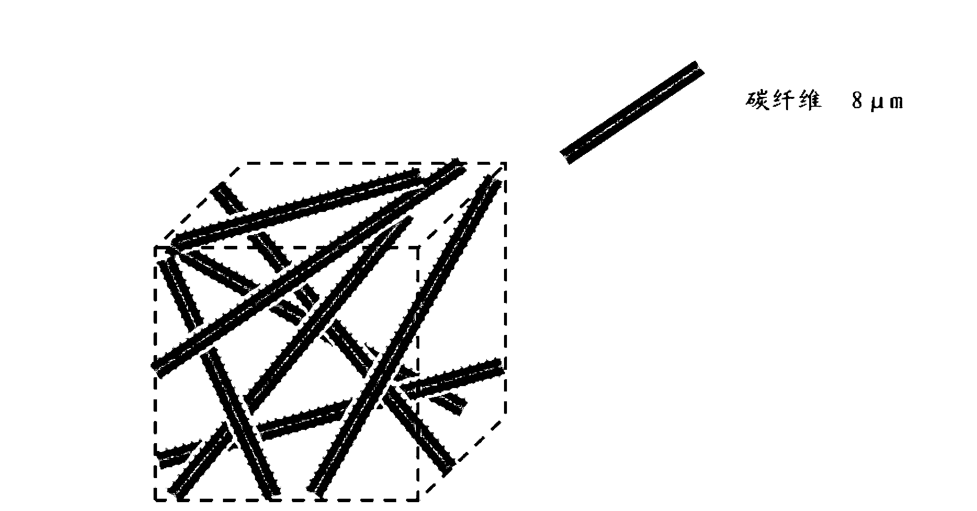
[0022] Step 1: Choose a density of 0.2g / cm 3 Chopped carbon fiber preforms serve as skeletons;
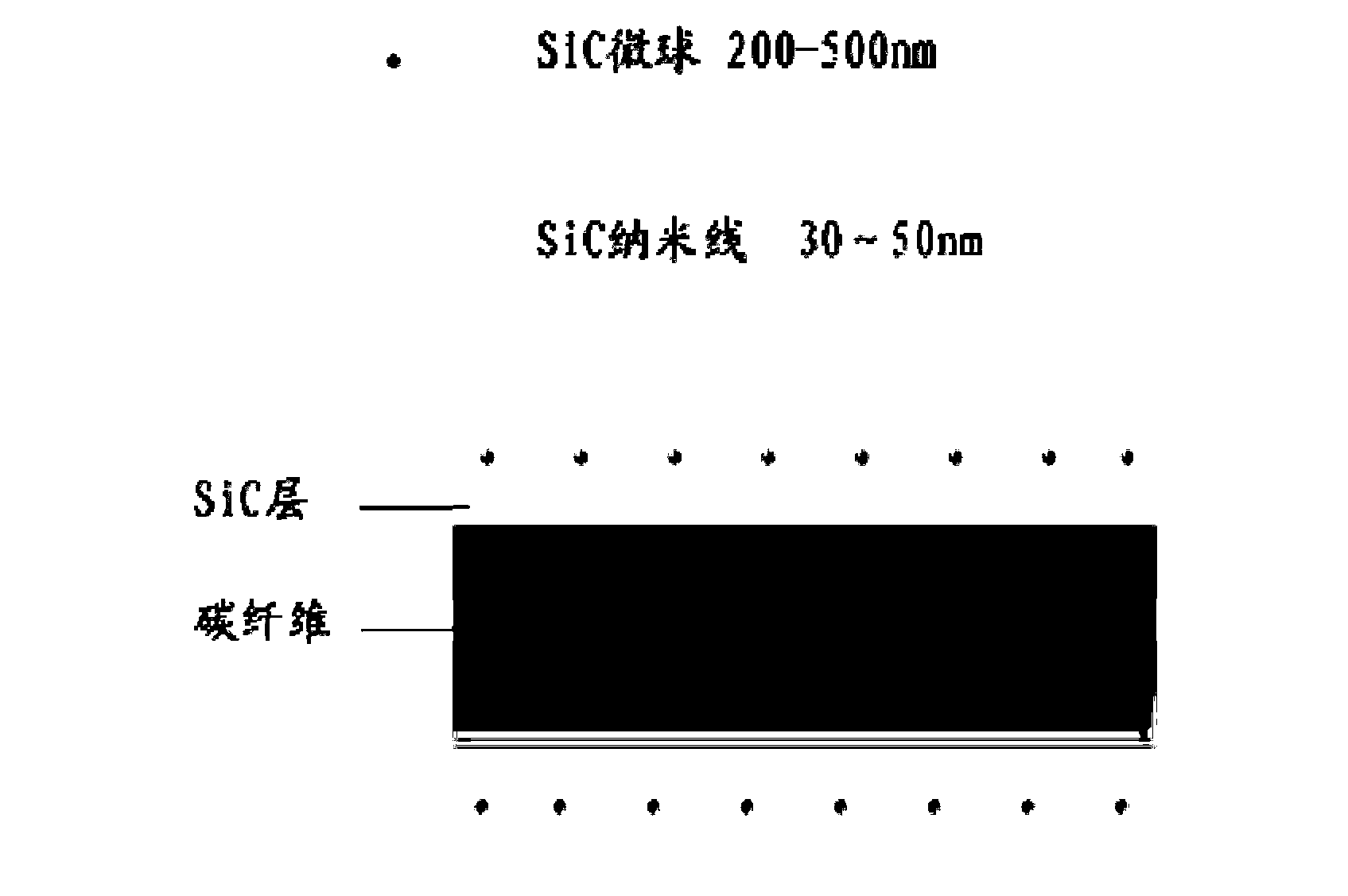
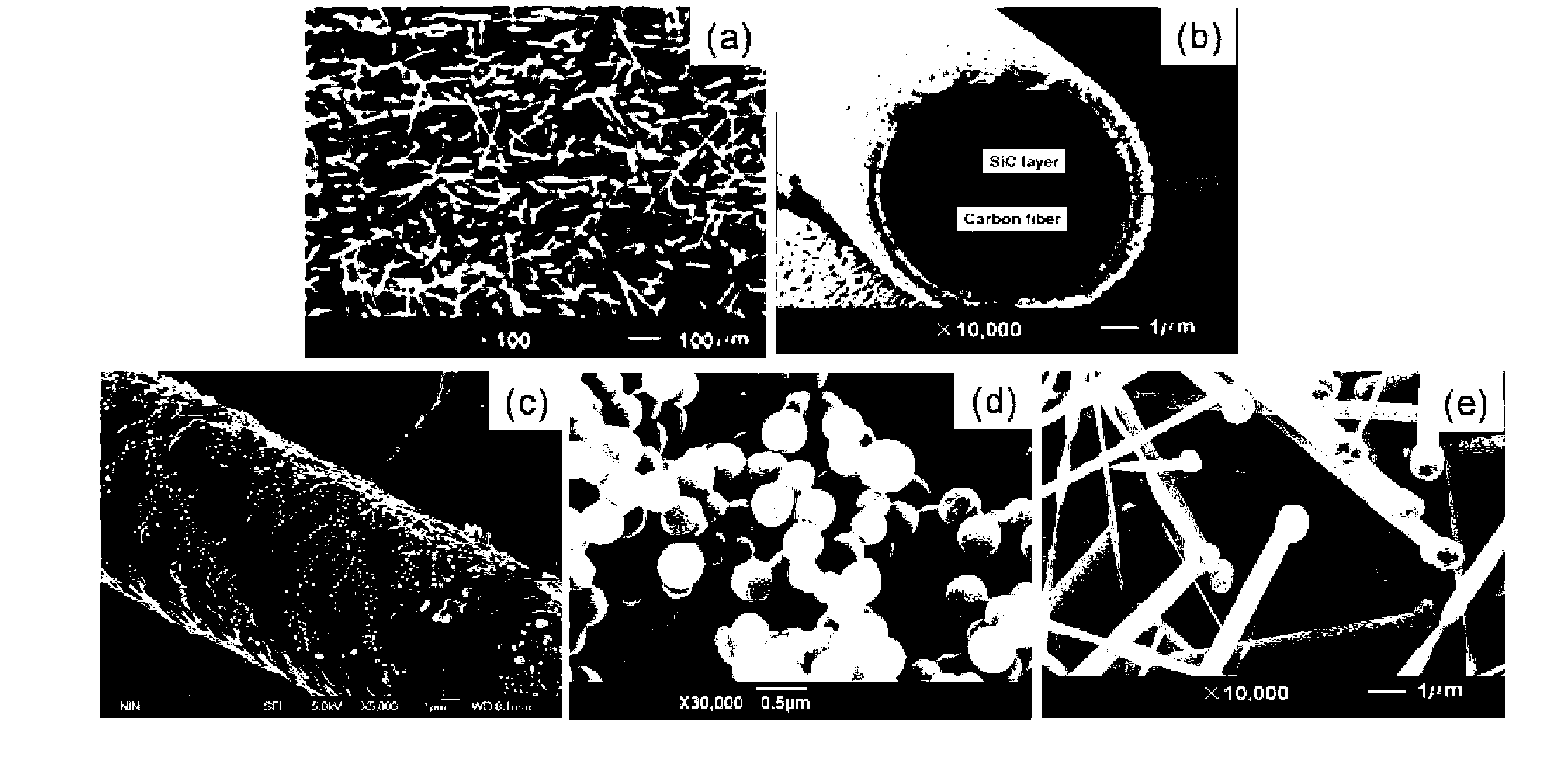
[0023] Step 2: Put the carbon fiber skeleton selected in step 1 into a chemical vapor deposition furnace, using natural gas as the carbon source precursor, the deposition temperature is 900°C, the deposition time is 1, and the thickness of the deposited pyrolytic carbon layer is 1 μm.
[0024] Step 3: Put the carbon fiber skeleton treated in step 2 into a microwave hydrothermal reaction apparatus. Using glucose as a carbon source, carbon microspheres were deposited on the surface of carbon fibers. The glucose concentration was controlled at 10g / L, the reaction temperature was controlled at 150°C, the reaction time was controlled at 1h, and the final carbon microsphere size was 200nm.
[0025] Step 4: Put the porous carbon template obtained in Step 3 into a microwave hydrothermal reactor. With Fe (NO 3 ) 3 As a raw material, nano-Fe was introduced into the porous carbon templat...
Embodiment 2
[0029] Step 1: Select a density of 0.6g / cm 3 Chopped carbon fiber preforms serve as skeletons;
[0030] Step 2: Put the carbon fiber skeleton selected in step 1 into a chemical vapor deposition furnace, using propane as the carbon source precursor, the deposition temperature is 1200°C, the deposition time is 4h, and the thickness of the deposited pyrolytic carbon layer is 5 μm.
[0031] Step 3: Put the carbon fiber skeleton treated in step 2 into a microwave hydrothermal reaction apparatus. Using glucose as a carbon source, carbon microspheres were deposited on the surface of carbon fibers. The glucose concentration was controlled at 100g / L, the reaction temperature was controlled at 250°C, the reaction time was controlled at 5h, and the final carbon microsphere size was 500nm.
[0032] Step 4: Put the porous carbon template obtained in Step 3 into a microwave hydrothermal reactor. With Ni (NO 3 ) 2 As a raw material, nano-NiO particles were introduced into the porous car...
Embodiment 3
[0036] Step 1: Choose a density of 0.4g / cm 3 Chopped carbon fiber preforms serve as skeletons;
[0037] Step 2: Put the carbon fiber skeleton selected in step 1 into a chemical vapor deposition furnace, using methane as the carbon source precursor, the deposition temperature is 1100 ° C, the deposition time is 2 h, and the thickness of the deposited pyrolytic carbon layer is 2 μm.
[0038] Step 3: Put the carbon fiber skeleton treated in step 2 into a microwave hydrothermal reaction apparatus. Using glucose as a carbon source, carbon microspheres were deposited on the surface of carbon fibers. The glucose concentration was controlled at 30g / L, the reaction temperature was controlled at 200°C, the reaction time was controlled at 3h, and the final carbon microsphere size was 300nm.
[0039] Step 4: Put the porous carbon template obtained in Step 3 into a microwave hydrothermal reactor. Take Co(NO 3 ) 2 As a raw material, nano-CoO particles were introduced into the porous ca...
PUM
| Property | Measurement | Unit |
|---|---|---|
| Size | aaaaa | aaaaa |
| Size | aaaaa | aaaaa |
| Thickness | aaaaa | aaaaa |
Abstract
Description
Claims
Application Information
 - R&D
- Intellectual Property
- Life Sciences
- Materials
- Tech Scout
- Unparalleled Data Quality
- Higher Quality Content
- 60% Fewer Hallucinations
Browse by: Latest US Patents, China's latest patents, Technical Efficacy Thesaurus, Application Domain, Technology Topic, Popular Technical Reports.
© 2025 PatSnap. All rights reserved.Legal|Privacy policy|Modern Slavery Act Transparency Statement|Sitemap|About US| Contact US: help@patsnap.com


