Membrane reactor

一种膜反应器、电解质隔膜的技术,应用在有机隔膜、电化学发生器、可持续制造/加工等方向,能够解决催化剂利用率和产率低等问题,达到转化率高的效果

Active Publication Date: 2013-06-19
TSINGHUA UNIV +1
View PDF8 Cites 17 Cited by
  • Summary
  • Abstract
  • Description
  • Claims
  • Application Information

AI Technical Summary

Problems solved by technology

However, the air diffusion electrode of this scheme has low catalyst utilization and yield.

Method used


Image

  • Membrane reactor
  • Membrane reactor
  • Membrane reactor

Examples


Embodiment 1

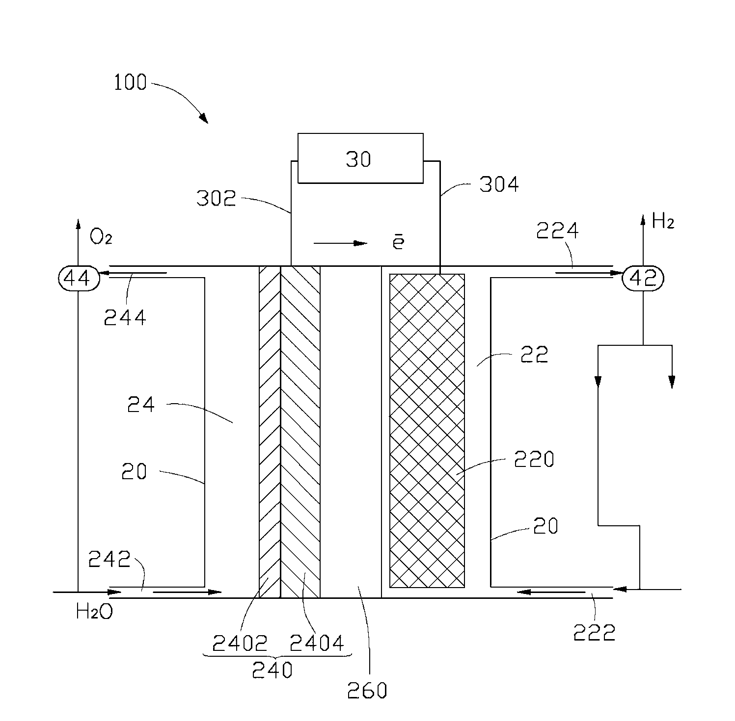
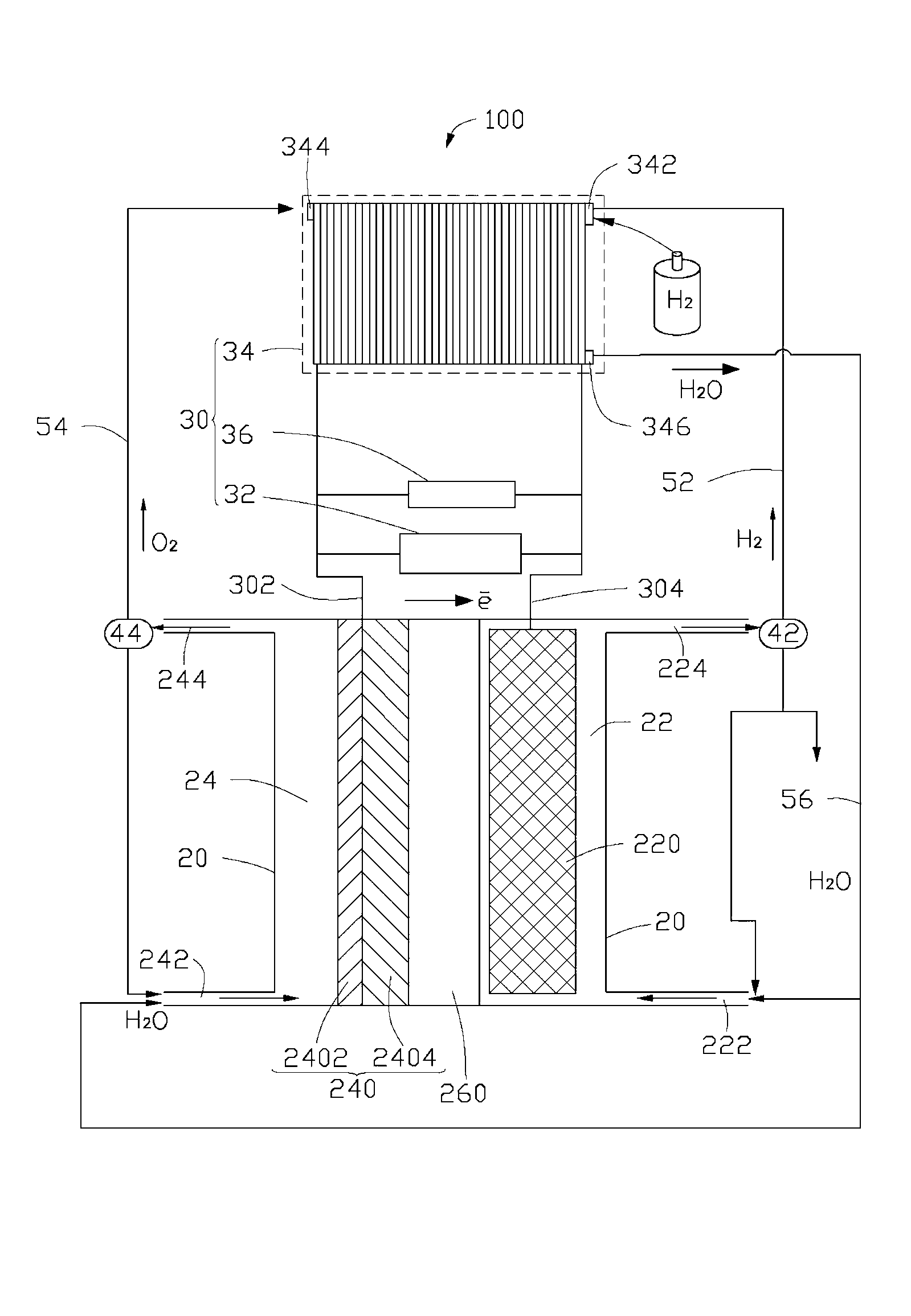
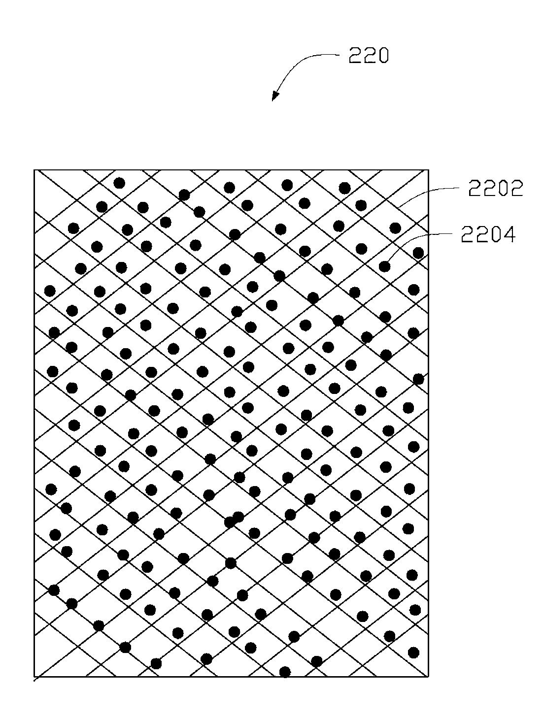
[0044] CO 2 The cathode 220 of the membrane reactor 10 used in the electrochemical reduction conversion uses a 10 mm thick porous titanium mesh as the porous support layer, and the porous support layer has an opening ratio of 60%. Highly dispersed Sn / Cu alloy particles are selected as the cathode catalyst, and the cathode catalyst particles are uniformly deposited in the pores of the porous support layer. In the anode 240, graphite carbon paper is used as the porous diffusion layer 2402, Ni powder is selected as the anode catalyst, and the Ni powder is plated on the surface of the graphite carbon paper to form the anode 240. The electrolyte diaphragm 260 is a perfluorosulfonic acid cation exchange membrane reinforced with polytetrafluoroethylene mesh, and the electrolyte diaphragm 260 and the anode 240 are hot-pressed to form a composite structure. The thickness of the perfluorosulfonic acid cation exchange membrane is 150 microns. An air-cooled proton exchange membrane fuel...

Embodiment 2

[0047] The structure of this embodiment membrane reactor 10 and the membrane reactor in embodiment 1 and CO 2 The electrochemical conversion process is basically the same, the difference is:

[0048] The porous support layer of the cathode 220 of the membrane reactor 10 is a porous nickel mesh with a thickness of 2.1 mm and a porosity of 31%. The cathode catalyst adopts Cd / In alloy, and is electroplated on the supporting frame of the porous nickel mesh. The anode catalyst uses MnO 2 and Ag powder mixture. The electrolyte diaphragm 260 is a perfluorocarboxylic acid cation exchange membrane reinforced by a porous polytetrafluoroethylene membrane. The enhanced perfluorocarboxylic acid cation exchange membrane has a thickness of 52 microns. A self-humidifying proton exchange membrane fuel cell is used as the electrochemical power source 34 . CO 2 Produced by winter heating boilers. Catholyte using KHCO 3 of aqueous solution. The electrolysis voltage is 3.5V. The product ...

Embodiment 3

[0050] The structure of the membrane reactor 10 in this embodiment and the membrane reactor 10 in Example 1 and the CO 2 The electrochemical conversion process is basically the same, the difference is:

[0051] The porous support layer of the cathode 220 of the membrane reactor 10 is a porous stainless steel mesh with a thickness of 20 mm and a porosity of 90%. The cathode catalyst adopts mixed particles of Bi and Zn, and is electroplated on the support skeleton of the porous stainless steel mesh. Porous nickel mesh is used as the porous diffusion layer 2402 of the anode 240, and the anode catalyst is LaNi 5 and Co powder mixture, LaNi 5 and Co powder are sprayed on the porous diffusion layer 2402 to form the anode catalyst layer 2404 . The electrolyte diaphragm 260 is a reinforced perfluorosulfonic acid / carboxylic acid composite cation exchange membrane. The perfluorosulfonic acid / carboxylic acid composite cation exchange membrane has a thickness of 200 microns. A solid ...


PUM

PropertyMeasurementUnit
particle diameteraaaaaaaaaa
pore sizeaaaaaaaaaa
current efficiencyaaaaaaaaaa

Abstract

The invention relates to a membrane reactor used for converting carbon dioxide into an expected product through electrochemical conversion. The membrane reactor comprises a power source and a chamber. An electrolyte separation membrane is arranged in the chamber, and divides the chamber into a cathode chamber and an anode chamber. An anode is arranged in the anode chamber, and a cathode is arranged in the cathode chamber. The power source comprises a positive electrode end and a negative electrode end. The positive electrode end is electrically connected with the anode, and the negative electrode end is electrically connected with the cathode. The negative electrode has a trickle-bed structure, and comprises a porous conductive supporting layer and a cathode catalyst arranged on the porous conductive supporting layer. The membrane reactor has good carbon dioxide electrochemical conversion utilization efficiency and energy circulation utilization rate.

Description

technical field [0001] The invention relates to a membrane reactor, in particular to a membrane reactor for electrochemical reduction conversion and utilization of carbon dioxide. Background technique [0002] The resource depletion problem with fossil energy as the core and the environmental problem with climate change as the core are the two major crises facing mankind at present. In the hundreds of years since the Industrial Revolution, the extensive use of fossil energy has led to a shortage of resources and a serious negative impact on the environment. The global environmental problem centered on global warming has become increasingly serious and has become a major threat to the sustainable development of mankind. One of the factors, reducing greenhouse gas emissions to slow down climate change has become a focus of attention of the international community today. The consumption of a large amount of carbon-containing energy accelerates the CO 2 emission rate, breaking...

Claims


Application Information

Patent Timeline
Patent Type & Authority Applications(China)
IPC IPC(8): C25B9/06C25B9/08C25B13/08C25B3/04C25B11/06C25B9/17C25B3/25C25B9/19
CPCC25B15/08C25B1/02H01M16/003Y02P20/10Y02E60/50C25B9/40C25B3/25C25B9/19Y02E60/36
Inventor 王诚赵晨辰刘志祥郭建伟何向明
Owner TSINGHUA UNIV
Why Eureka
Try Eureka