Flue gas desulphurization and denitration method as well as its apparatus

A technology for desulfurization, denitrification, and flue gas, which is applied in separation methods, chemical instruments and methods, and separation of dispersed particles. It can solve problems such as low flue gas temperature and large equipment volume, and achieve simplified equipment structure, small volume, and reduced pressure loss. Effect

Active Publication Date: 2014-02-19
湖州旧馆頔南污水处理有限公司
View PDF12 Cites 35 Cited by
  • Summary
  • Abstract
  • Description
  • Claims
  • Application Information

AI Technical Summary

Problems solved by technology

However, when SCR is applied to heavy-duty diesel engine exhaust denitrification, there are still pro

Method used


Image

  • Flue gas desulphurization and denitration method as well as its apparatus
  • Flue gas desulphurization and denitration method as well as its apparatus
  • Flue gas desulphurization and denitration method as well as its apparatus

Examples


Embodiment 1

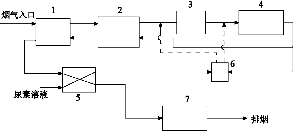
[0040] Such as figure 2 Shown is the flue gas desulfurization and denitrification method and device of the present invention, the method is used for desulfurization and denitrification of flue gas from a marine diesel engine with a power of 550kW and a rotation speed of 750rpm. The exhaust temperature of the diesel engine drops to about 250°C at low speed, the maximum flow of flue gas is 4.4t / h, NO x Weighted emissions are 9.6g / kWh. When the system starts and stops, the flue gas passes through passage 1 to react with the incoming solid particles and enters the flue gas heating process after passing through the dust collector. When the system is in normal operation, the flue gas directly enters the flue gas heating process through passage 2. The flue gas first enters the heat exchanger for heat exchange and temperature rise, so that the temperature of the flue gas rises to about 290°C. The heated smoke is raised to about 340°C by a heat pump, and then the flue gas is heated b...

Embodiment 2

[0044] This embodiment is basically the same as the embodiment 1, the difference is that: both sides of the heat transfer surface of the flue gas partition wall of the heat exchanger are coated with a coating that enhances heat radiation, and the heat radiation absorption rate of the coated coating layer is 0.95. The product of urea hydrolysis and a part of the SCR reactor outlet flue gas enter the static mixer, and the NH in the mixed gas 3 The volume fraction reaches 8%, and it is sprayed into the pipeline between the electric heater and the SCR reactor through the ammonia injection grid.

Embodiment 3

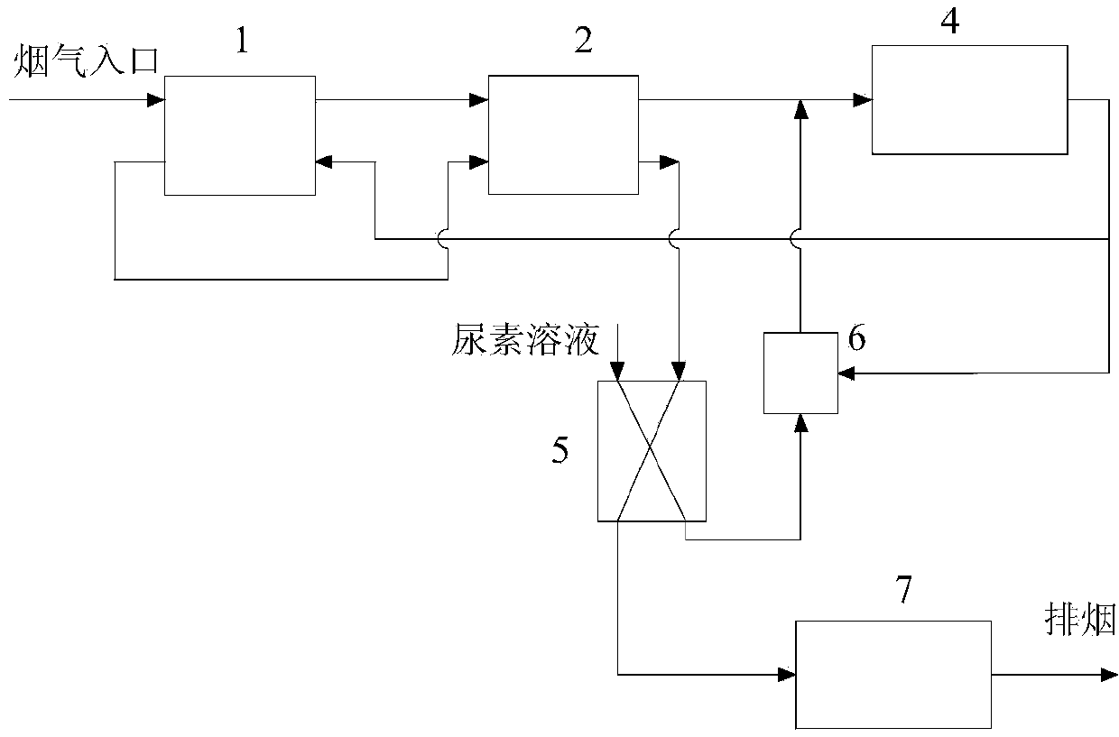
[0046] Such as image 3 Shown is the flue gas desulfurization and denitrification method and device of the present invention, the method is used for desulfurization and denitrification of flue gas from a marine diesel engine with a power of 1500kW and a rotational speed of 1760rpm. The exhaust temperature of the diesel engine drops to about 260°C at low speed, the maximum flow of flue gas is 13.6t / h, NO x Weighted emissions are 9.38g / kWh. When the system starts and stops, the flue gas passes through passage 1 to react with the incoming solid particles and enters the flue gas heating process after passing through the dust collector. When the system is in normal operation, the flue gas directly enters the flue gas heating process through passage 2. The flue gas first enters the heat exchanger for heat exchange and temperature rise, so that the temperature of the flue gas rises to about 320°C, and the temperature of the heated smoke is raised to about 380°C through the heat pump...


PUM

PropertyMeasurementUnit
Particle sizeaaaaaaaaaa

Abstract

The invention relates to a flue gas desulphurization and denitration method as well as its apparatus, and especially relates to a desulphurization and denitration technology system for flue gas from large-scale mobile facilities such as ships. The method comprises the following steps: flue gas is passed through a heat pipe exchanger and a heat pump in order for increasing temperature of flue gas, and flue gas is selectively passed through an electric heater for heating to the temperature of 340-350 DEG C, an urea solution is used for preparing ammonia gas in a hydrolysis reactor, ammonia gas is diluted by partial high temperature flue gas at an outlet of a SCR reactor and then mixed for injecting flue gas which is undenitrated, the mixed flue gas enters into the SCR reactor for a flue gas denitration reaction, the flue gas after denitration is passed through the heat exchanger, the heat pump and the hydrolysis reactor and cooled, and then enters into a desulfurization tower, flue gas after desulphurization is directly discharged into atmosphere, and an absorption liquid adds alkali and seawater for regeneration and cycle usage. In the method, the heat exchanger and the heat pump are used for recovering waste heat of flue gas, and the energy consumption is greatly reduced. The ammonia production method through hydrolysis is capable of increasing the mixing degree of ammonia and flue gas, so that denitration efficiency can be further increased.

Description

technical field [0001] The invention relates to a method and device for desulfurization and denitrification of flue gas, in particular to a method and device for desulfurization and denitrification of flue gas of large mobile facilities such as ships, and belongs to the field of energy conservation and environmental protection. Background technique [0002] With the increasing concern of the international community on marine environmental pollution, the pollution of ship flue gas is becoming more and more prominent, among which nitrogen oxides (NO x ) and sulfur dioxide are the most harmful to the ecological environment in diesel engine emissions. Environmental protection requirements gradually increase, NO x and SO 2 Emission requirements are becoming more and more stringent. In order to prevent, reduce and control air pollution caused by marine diesel engine exhaust, MARPOL Annex VI "Regulations for the Prevention of Air Pollution from Ships" formulated by the Internati...

Claims


Application Information

Patent Timeline
IPC IPC(8): B01D53/75B01D53/56B01D53/50
Inventor 张书廷赵旭张利亚
Owner 湖州旧馆頔南污水处理有限公司
Why Eureka
Try Eureka