Method for improving corrosion resistance of sintered neodymium iron boron magnet

A neodymium-iron-boron, corrosion-resistant technology, used in inductor/transformer/magnet manufacturing, coating, laser welding equipment, etc. Intrinsic corrosion resistance, simple process, and the effect of improving physical and chemical properties

Active Publication Date: 2014-03-26
东台城东科技创业园管理有限公司
View PDF0 Cites 24 Cited by
  • Summary
  • Abstract
  • Description
  • Claims
  • Application Information

AI Technical Summary

Problems solved by technology

The surface coating method improves the corrosion resistance by plating a corrosion-resistant protective coating on the surface of the magnet. Low binding force and not environmentally friendly

Method used


Image

  • Method for improving corrosion resistance of sintered neodymium iron boron magnet
  • Method for improving corrosion resistance of sintered neodymium iron boron magnet

Examples


Embodiment 1

[0023] 1) The sintered NdFeB magnet Nd 9 PR 3 Fe 80 co 2 B 5.5 Cu 0.5 Grinding, polishing, cleaning and drying pretreatment on the surface to be processed;

[0024] 2) Clamp the pretreated sintered NdFeB magnet on the workbench;

[0025] 3) Under vacuum, irradiate the surface of the sintered NdFeB magnet to be processed with continuous laser to melt the grain boundary phase to form a micro-melt pool. The laser power is 500W, the scanning speed is 5mm / s, the spot diameter is 2mm, and the overlap rate is 20%;

[0026] 4) Send 20nm metal Al nanopowder into the grain boundary micro-melting pool through the powder feeding device, so that it can be microalloyed with the grain boundary phase;

[0027] 5) The unalloyed nanopowder is cleaned up to obtain a sintered NdFeB magnet modified by surface grain boundary selective microalloying.

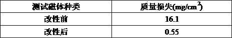
[0028] The corrosion resistance of sintered NdFeB magnets before and after surface modification was tested by autoclave experiment (5-10psig, ...

Embodiment 2

[0031] 1) The sintered NdFeB magnet Nd 13 PR 3 Dy 2 Fe 73 B 8 Al 0.5 Ga 0.5Grinding, polishing, cleaning and drying pretreatment on the surface to be processed;

[0032] 2) Clamp the pretreated sintered NdFeB magnet on the workbench;

[0033] 3) Under the protection of argon gas, the surface to be processed of the sintered NdFeB magnet is irradiated with pulsed laser until the grain boundary phase is melted to form a micro molten pool, and the laser power density is 1MW / cm 2 , pulse width 100ns, overlap rate 80%;

[0034] 4) Send 100nm compound SiC nanopowder into the grain boundary micro-melting pool through the powder feeding device, so that it can be microalloyed with the grain boundary phase;

[0035] 5) The unalloyed nanopowder is cleaned up to obtain a sintered NdFeB magnet modified by surface grain boundary selective microalloying.

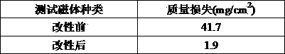
[0036] The corrosion resistance of sintered NdFeB magnets before and after surface modification was tested by autoclave experimen...

Embodiment 3

[0039] 1) The sintered NdFeB magnet Nd 14 Tb 0.1 Fe 79.8 B 6 Zr 0.1 Grinding, polishing, cleaning and drying pretreatment on the surface to be processed;

[0040] 2) Clamp the pretreated sintered NdFeB magnet on the workbench;

[0041] 3) Under the protection of helium, the surface of the sintered NdFeB magnet to be processed is irradiated with continuous laser to melt the grain boundary phase to form a micro-melt pool. The laser power is 100W, the scanning speed is 20mm / s, the spot diameter is 0.5mm, and the overlap rate is 80 %;

[0042] 4) Send the mixed powder of 60nm metal Cu and 100nm metal Co nanopowder with a volume ratio of 2:1 into the grain boundary micro-melting pool through the powder feeding device, so that it can be microalloyed with the grain boundary phase;

[0043] 5) The unalloyed nanopowder is cleaned up to obtain a sintered NdFeB magnet modified by surface grain boundary selective microalloying.

[0044] The corrosion resistance of sintered NdFeB ma...


PUM

PropertyMeasurementUnit
particle sizeaaaaaaaaaa

Abstract

The invention discloses a method for improving the corrosion resistance of a sintered neodymium iron boron magnet, and relates to a permanent magnet material surface modification technology. The method mainly comprises the following steps: 1, carrying out sanding, polishing, cleaning and drying pretreatment of a sintered neodymium iron boron magnet surface for processing; 2, clamping the above obtained pretreated sintered neodymium iron boron magnet on a workbench; 3, carrying out laser irradiation of the sintered neodymium iron boron magnet surface for processing under the protection of vacuum or a gas until a grain boundary phase melts to form a micro melting pool; 4, sending metal or compound nano-powder into the grain boundary micro melting pool through a powder sending device for the micro-alloying of the nano-powder and the grain boundary phase; and 5, cleaning up unalloyed nano-powder to obtain a sintered neodymium iron boron magnet with a selectively alloying modified surface grain boundary. The method can effectively change the component and structure of the magnet surface grain boundary phase, can improve the physical and chemical properties of the grain boundary phase, can inhibit the intercrystalline corrosion of the surface of the magnet, and can substantially improve the corrosion resistance of the magnet. The method has the advantages of simple process, easy operation, and suitableness for the large-scale batch production.

Description

[0001] technical field [0002] The invention relates to the technical field of surface modification of permanent magnet materials, in particular to a method for improving the corrosion resistance of sintered NdFeB magnets. Background technique [0003] Sintered NdFeB magnets are a new generation of rare earth permanent magnet materials developed in the early 1980s. They have excellent magnetic properties and high cost performance, and have been widely used in microwave communications, audio-visual technology, instrumentation, electrical engineering, computers, and medical equipment. And other fields, become the pillar of the permanent magnet industry. However, the disadvantage of poor corrosion resistance of sintered NdFeB magnets severely limits its application range. [0004] The poor corrosion resistance of sintered NdFeB magnets is closely related to its own structure. Sintered NdFeB magnets have the main phase Nd 2 Fe 14 B. Multi-phase organization of neodymium-ric...

Claims


Application Information

Patent Timeline
Patent Type & Authority Applications(China)
IPC IPC(8): C23C24/10B22F1/00H01F41/02B23K26/34
Inventor 崔熙贵崔承云程晓农许晓静
Owner 东台城东科技创业园管理有限公司
Why Eureka
Try Eureka