Production method for infrared radiation reflecting film
A manufacturing method, infrared technology, applied in chemical instruments and methods, sputtering plating, ion implantation plating, etc., can solve problems such as deterioration, insufficient physical strength such as scratch resistance, and achieve the effect of improving productivity
- Summary
- Abstract
- Description
- Claims
- Application Information
AI Technical Summary
Problems solved by technology
Method used
Image
Examples
preparation example Construction
[0090] The solvent used for the preparation of these solutions is not particularly limited as long as it is a solvent capable of dissolving each of the above-mentioned materials. For example, low-boiling-point solvents such as methyl ethyl ketone (MEK) and methylene chloride can be used suitably. In addition, the solution for forming the transparent protective layer may contain coupling agents such as silane coupling agents and titanium coupling agents, leveling agents, and ultraviolet absorbers in addition to polymers, monomers, and crosslinking agents. , antioxidants, heat stabilizers, lubricants, plasticizers, anti-coloring agents, flame retardants, antistatic agents and other additives. The contents of these additives can be appropriately adjusted within the range not impairing the object of the present invention.
[0091] A transparent protective layer can be formed by applying the above solution on the infrared reflective layer and drying the solvent. Curing of the poly...
Embodiment 1
[0121] Formation of hard coat at substrate
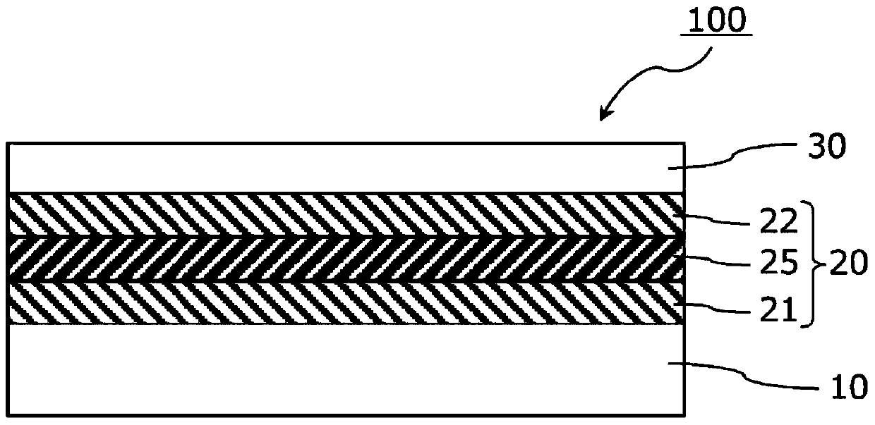
[0122] On one side of a polyethylene terephthalate film (manufactured by TORAY INDUSTRIES, INC., trade name "Lumirror U48", visible light transmittance: 93%) with a thickness of 50 μm, an acrylic ultraviolet curing type is formed with a thickness of 2 μm Hard coating (manufactured by Nippon Soda, NH2000G). Specifically, a hard coat solution was applied by a gravure coater, dried at 80°C, and then irradiated with a cumulative light intensity of 300mJ / cm by an ultra-high pressure mercury lamp. 2 UV light for curing.
[0123] Formation of infrared reflective layer
[0124] On the hard coat layer of the polyethylene terephthalate film substrate, an infrared reflective layer was formed using a roll-to-roll sputtering device. Specifically, a first metal oxide layer made of zinc-tin composite oxide (ZTO) with a film thickness of 30 nm and a metal layer made of an Ag-Pd alloy with a film thickness of 15 nm were sequentially formed by...
Embodiment 2~7
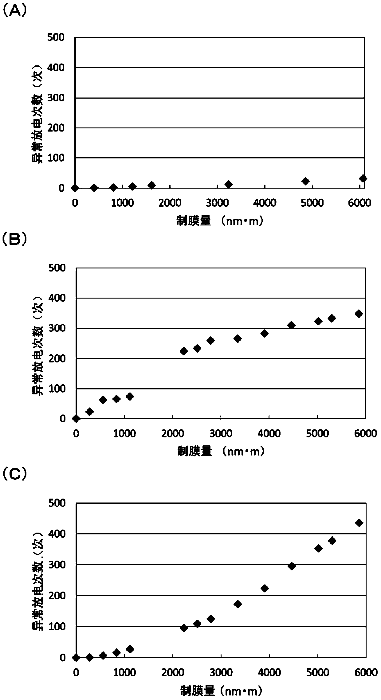
[0130] In the following Examples 2-7, except having changed the composition of the target used for film formation of a metal oxide layer, it carried out similarly to Example 1, and produced the infrared reflection film. In these examples, powder that would cause abnormal discharge during sputtering was not produced in the same manner as in Example 1, and the product of the thickness and length of the metal oxide layer could be continuously stabilized at 6000 nm·m. film formation without cleaning the target and sputtering device.
PUM
| Property | Measurement | Unit |
|---|---|---|
| electrical resistivity | aaaaa | aaaaa |
| thickness | aaaaa | aaaaa |
| thickness | aaaaa | aaaaa |
Abstract
Description
Claims
Application Information
 - R&D
- Intellectual Property
- Life Sciences
- Materials
- Tech Scout
- Unparalleled Data Quality
- Higher Quality Content
- 60% Fewer Hallucinations
Browse by: Latest US Patents, China's latest patents, Technical Efficacy Thesaurus, Application Domain, Technology Topic, Popular Technical Reports.
© 2025 PatSnap. All rights reserved.Legal|Privacy policy|Modern Slavery Act Transparency Statement|Sitemap|About US| Contact US: help@patsnap.com


