

Ion exchange membrane for reverse electrodialysis device and reverse electrodialysis device including same
A technology of cation-exchange membrane and anion-exchange membrane, applied in the field of reverse electrodialysis devices, which can solve the problems of high price of ion-exchange membranes in reverse electrodialysis systems, delay in commercialization, etc.
- Summary
- Abstract
- Description
- Claims
- Application Information
AI Technical Summary
Problems solved by technology
Method used
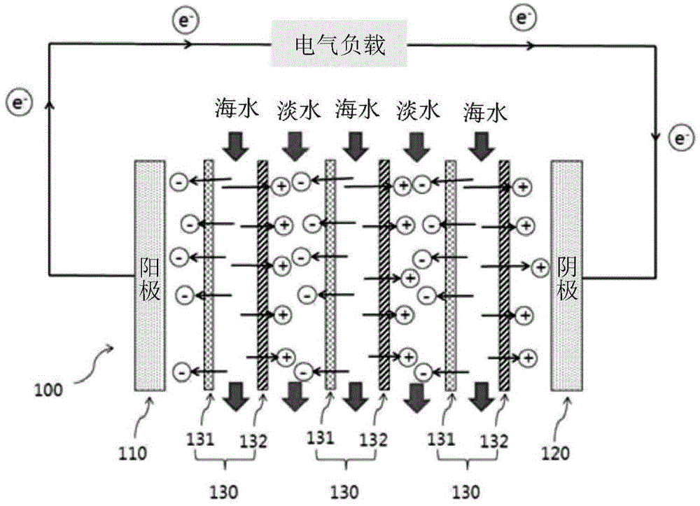
Image

Examples
Embodiment 1
[0106] Preparation of cation exchange membrane for reverse electrodialysis device
[0107] Mix and stir the high-concentration ethylene sulfonic acid of more than 95% without water: N, N'-vinylbisacrylamide in 80:20 parts by weight, the initiator is Darocur1173 diluted to methanol in 10 parts by weight, according to the above-mentioned This initiator was mixed with 100 parts by weight of the mixed solution at a rate of 1 part by weight.
[0108] Afterwards, a polyethylene porous support with a film thickness of 25 μm, a pore size of 0.07 μm, and a pore distribution of 45% was impregnated in the above solution to fully immerse the monomer solution in the support. Immerse in a commercially available surfactant (dodecylbenzenesulfonic acid, DBSA) diluted with 0.5 to 1 part by weight of water to form a solution for 1 to 2 minutes and then dry to hydrophilize the surface of the pores, and then place the support on Between polyethylene terephthalate (PET) films and become 150mJ / ...
Embodiment 2
[0111] Preparation of reverse electrodialysis device with anion exchange membrane
[0112](Vinylbenzyl)trimethylammonium chloride, 1,3,5-triacryloylhexahydro-1,3,5-triazine, deionized water and dimethylformamide according to 1: The mixed solvent of the weight ratio of 1 is mixed and stirred with the weight ratio of 61.5:15.4:23.1, and photoinitiator is the 2-hydroxyl-2 methyl-1-phenyl-1-ketone that is diluted to methyl alcohol with 10% by weight, according to and The photoinitiator was mixed in a ratio of 1 part by weight to 100 parts by weight of the mixed solution.
[0113] Afterwards, a polyolefin-based porous support with a film thickness of 25 μm, an average pore size of 0.07 μm, and a pore distribution of 45% was impregnated in the solution, and the monomer solution was fully immersed in the support. Next, the electrolyte-impregnated membrane is placed between polyethylene terephthalate (PET) membranes and becomes 30 to 150 mJ / cm 2 irradiated with ultraviolet energy...
Embodiment 3
[0115] Preparation of the reverse electrodialysis module comprising the ion exchange membrane made in Example 1 and Example 2
[0116] The anode and cathode (10cm×10cm, effective area 0.0071m) made after graphite electrode polishing 2 ) between the anion-exchange membrane made in the above-mentioned embodiment 2 and the cation-exchange membrane made in the above-mentioned embodiment 1 are installed in isolation by a spacer, in order to ensure that the electrode rinsing solution (50mM Fe(CN) 6 3+ / 4+ Aqueous solution and 0.5M Na 2 SO 4 Aqueous solution) flow channel to fabricate a reverse electrodialysis (RED) module equipped with a woven mesh type electrode separator (thickness 200 μm m) and a silicon gasket (silicon gasket).
[0117] Preparation of Reverse Electrodialysis Module Containing Commercial Ion Exchange Membrane
[0118] The reverse electrodialysis module was fabricated in the same way as in Example 3 except that the commercial cation exchange membrane ASTO...
PUM
| Property | Measurement | Unit |
|---|---|---|
| Pore size | aaaaa | aaaaa |
| Thickness | aaaaa | aaaaa |
Abstract
Description
Claims
Application Information