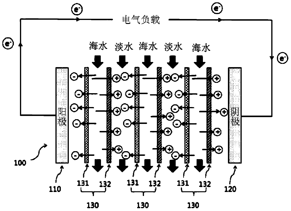
Ion exchange membrane for reverse electrodialysis device and reverse electrodialysis device comprising it
A cation exchange membrane and anion exchange membrane technology, applied in the field of reverse electrodialysis devices, can solve the problems of delaying the pace of commercialization and the high price of ion exchange membranes in reverse electrodialysis systems.
- Summary
- Abstract
- Description
- Claims
- Application Information
AI Technical Summary
Problems solved by technology
Method used
Image
Examples
Embodiment 1
[0106] Preparation of cation exchange membrane for reverse electrodialysis device
[0107] Mix and stir the high-concentration ethylene sulfonic acid of more than 95% without water: N, N'-vinylbisacrylamide in 80:20 parts by weight, the initiator is Darocur1173 diluted to methanol in 10 parts by weight, according to the above-mentioned This initiator was mixed with 100 parts by weight of the mixed solution at a rate of 1 part by weight.
[0108] Afterwards, a polyethylene porous support with a film thickness of 25 μm, a pore size of 0.07 μm, and a pore distribution of 45% was impregnated in the above solution to fully immerse the monomer solution in the support. Immerse in a commercially available surfactant (dodecylbenzenesulfonic acid, DBSA) diluted with 0.5 to 1 part by weight of water to form a solution for 1 to 2 minutes and then dry to hydrophilize the surface of the pores, and then place the support on Between polyethylene terephthalate (PET) films and become 150mJ / ...
Embodiment 2
[0111] Preparation of reverse electrodialysis device with anion exchange membrane
[0112](Vinylbenzyl)trimethylammonium chloride, 1,3,5-triacryloylhexahydro-1,3,5-triazine, deionized water and dimethylformamide according to 1: The mixed solvent of the weight ratio of 1 is mixed and stirred with the weight ratio of 61.5:15.4:23.1, and photoinitiator is the 2-hydroxyl-2 methyl-1-phenyl-1-ketone that is diluted to methyl alcohol with 10% by weight, according to and The photoinitiator was mixed in a ratio of 1 part by weight to 100 parts by weight of the mixed solution.
[0113] Afterwards, a polyolefin-based porous support with a film thickness of 25 μm, an average pore size of 0.07 μm, and a pore distribution of 45% was impregnated in the solution, and the monomer solution was fully immersed in the support. Next, the electrolyte-impregnated membrane is placed between polyethylene terephthalate (PET) membranes and becomes 30 to 150 mJ / cm 2 irradiated with ultraviolet energy...
Embodiment 3
[0115] Preparation of the reverse electrodialysis module comprising the ion exchange membrane made in Example 1 and Example 2
[0116] The anode and cathode (10cm×10cm, effective area 0.0071m) made after graphite electrode polishing 2 ) between the anion-exchange membrane made in the above-mentioned embodiment 2 and the cation-exchange membrane made in the above-mentioned embodiment 1 are installed in isolation by a spacer, in order to ensure that the electrode rinsing solution (50mM Fe(CN) 6 3+ / 4+ Aqueous solution and 0.5M Na 2 SO 4 Aqueous solution) flow path to fabricate a reverse electrodialysis (RED) module equipped with a woven mesh type electrode separator (thickness 200 μm m) and a silicon gasket (silicongasket).
[0117] Preparation of Reverse Electrodialysis Module Containing Commercial Ion Exchange Membrane
[0118] The reverse electrodialysis module was fabricated in the same way as in Example 3 except that the commercial cation exchange membrane ASTOM Ne...
PUM
| Property | Measurement | Unit |
|---|---|---|
| pore size | aaaaa | aaaaa |
| thickness | aaaaa | aaaaa |
Abstract
Description
Claims
Application Information
 - R&D
- Intellectual Property
- Life Sciences
- Materials
- Tech Scout
- Unparalleled Data Quality
- Higher Quality Content
- 60% Fewer Hallucinations
Browse by: Latest US Patents, China's latest patents, Technical Efficacy Thesaurus, Application Domain, Technology Topic, Popular Technical Reports.
© 2025 PatSnap. All rights reserved.Legal|Privacy policy|Modern Slavery Act Transparency Statement|Sitemap|About US| Contact US: help@patsnap.com


