Continuous recovery device and continuous recovery process of vanadium, molybdenum and titanium in SCR (selective catalytic reduction) waste catalyst

A waste catalyst and recycling device technology, applied in the field of solid waste recycling, can solve the problems of unfavorable large-scale application, harsh recycling conditions, and high operating costs, and achieve the effects of low recycling costs, easy conditions, and reduced operating costs.

Active Publication Date: 2015-03-25
DATANG NANJING ENVIRONMENTAL PROTECTION TECH
View PDF2 Cites 27 Cited by
  • Summary
  • Abstract
  • Description
  • Claims
  • Application Information

AI Technical Summary

Problems solved by technology

[0004] At present, most catalyst recovery technologies focus on the recovery of honeycomb catalysts, and there are few reports on the recovery of flat-plate catalysts. In addition, most of the recovery technologies reported are batch processes with harsh recovery conditions, high operating costs, and large amounts of wastewater. Not conducive to large-scale application

Method used


Image

  • Continuous recovery device and continuous recovery process of vanadium, molybdenum and titanium in SCR (selective catalytic reduction) waste catalyst
  • Continuous recovery device and continuous recovery process of vanadium, molybdenum and titanium in SCR (selective catalytic reduction) waste catalyst
  • Continuous recovery device and continuous recovery process of vanadium, molybdenum and titanium in SCR (selective catalytic reduction) waste catalyst

Examples


Embodiment 1

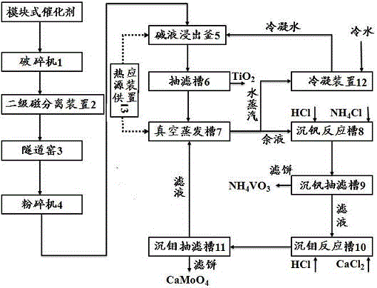
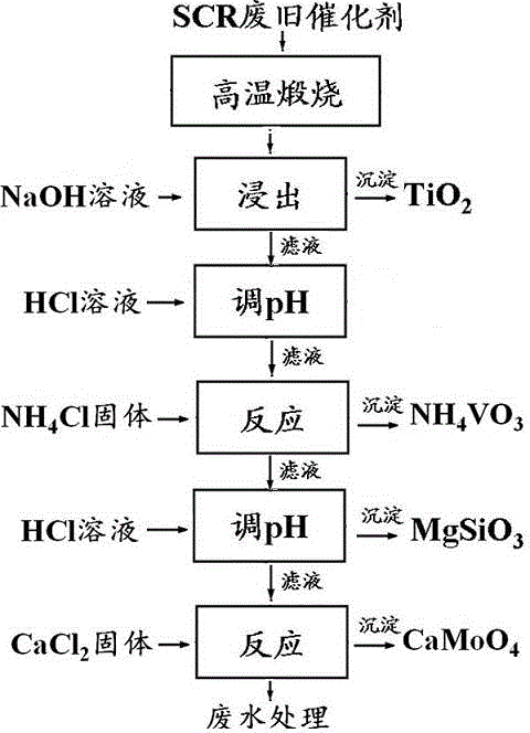
[0040] Such as figure 1 with figure 2 As shown, in this embodiment, a comprehensive recovery process and device for recovering V, Mo and Ti in spent SCR catalysts by alkaline leaching are carried out according to the following steps.

[0041] The flat-plate waste flue gas denitrification catalyst is physically crushed by the crusher to obtain steel mesh, iron filings and catalyst powder, which enters the secondary magnetic separation device through the conveyor belt to separate the steel mesh and iron filings, and the remaining catalyst powder enters the tunnel kiln at 850°C Calcination was continued for 4 h, and the obtained sintered agglomerate was sent into a pulverizer through a conveyor belt to be pulverized to more than 100 mesh, and then the powder was put into a reaction kettle containing a hot NaOH solution with a concentration of 20 wt% (relative to the weight of the spent catalyst) at a temperature of 80-90 °C , the bottom of the reactor is equipped with an aerat...

Embodiment 2

[0047] Such as figure 1 with figure 2 As shown, in this embodiment, a comprehensive recovery process and device for recovering V, Mo and Ti in spent SCR catalysts by alkaline leaching are carried out according to the following steps.

[0048] The flat-plate waste flue gas denitrification catalyst is physically crushed by the crusher to obtain steel mesh, iron filings and catalyst powder, which enters the secondary magnetic separation device through the conveyor belt to separate the steel mesh and iron filings, and the remaining catalyst powder enters the tunnel kiln at 750°C Continuous calcination for 4 h, the obtained sintered agglomerate was sent into the pulverizer through the conveyor belt and crushed to more than 100 mesh, and then the powder entered the reactor containing hot NaOH solution with a temperature of about 85 °C and a concentration of 20 wt% (relative to the weight of the spent catalyst). There is an aeration device at the bottom of the reactor, so that the...

Embodiment 3

[0055] Such as figure 1 with figure 2 As shown, in this embodiment, a comprehensive recovery process and device for recovering V, Mo and Ti in spent SCR catalysts by alkaline leaching are carried out according to the following steps.

[0056] The flat-plate waste flue gas denitrification catalyst is physically crushed by the crusher to obtain steel mesh, iron filings and catalyst powder, which enters the secondary magnetic separation device through the conveyor belt to separate the steel mesh and iron filings, and the remaining catalyst powder enters the tunnel kiln at 750°C Calcination was continued for 4 h, and the obtained sintered agglomerate was sent into a pulverizer through a conveyor belt to be pulverized to a size above 100 mesh, and then the powder was put into a reaction kettle containing a hot NaOH solution with a temperature of about 85 °C and a concentration of 30 wt% (relative to the weight of the spent catalyst). There is an aeration device at the bottom of ...


PUM


Abstract

The invention discloses a continuous recovery device and a continuous recovery process of vanadium, molybdenum and titanium in an SCR (selective catalytic reduction) waste catalyst, wherein a crusher is connected with a secondary magnetic separation device, the secondary magnetic separation device is connected with a tunnel kiln, the tunnel kiln is connected with a smasher, the smasher is connected with an alkaline leaching kettle, the alkaline leaching kettle is connected with a suction filtration groove, the suction filtration groove is connected with a vacuum evaporation tank, the vacuum evaporation tank is connected with a vanadium sedimentation reaction tank, and the vanadium sedimentation reaction tank is connected with a molybdenum sedimentation suction filtration groove; the alkaline leaching kettle is clamped outside the reaction kettle, a top overflow opening is positioned in the upper side of the jacket, a charging opening and a filling opening are positioned in the upper part of the reaction kettle, and the filling opening is guided to the middle part of the reaction kettle by virtue of a guide pipe. According to the continuous device disclosed by the invention, the production efficiency is effectively improved, thereby facilitating subsequent automatic and continuous production. A flat plate type flue gas denitrification catalyst is continuously recovered, infiltrating water is recycled, and the water yield is greatly saved.

Description

technical field [0001] The invention relates to a continuous recovery device and recovery process for vanadium, molybdenum and titanium in SCR waste catalysts, belonging to the field of solid waste recovery. Background technique [0002] Selective Catalytic Reduction (SCR) flue gas denitrification technology has become a popular choice for coal-fired flue gas nitrogen oxides (NO X ) removal mainstream technology. Currently, V 2 o 5 -MoO 3 -TiO 2 The monolithic catalyst is one of the most widely used SCR flue gas denitrification catalysts. The catalyst is based on TiO 2 as the carrier, V 2 o 5 and MoO 3 as the active ingredient. TiO in flue gas denitrification catalyst 2 The mass fraction is 80%~90%, V 2 o 5 The mass fraction is 1~5%, MoO 3 The mass fraction is 5~10%. [0003] Since the optimal activation temperature of this type of SCR catalyst is 350-400 °C, the SCR denitrification system is generally placed between the economizer and the air preheater in the ...

Claims


Application Information

Patent Timeline
Patent Type & Authority Applications(China)
IPC IPC(8): C22B7/00C22B34/12C22B34/22C22B34/34
Inventor 钟秦于爱华江晓明王虎丁杰董岳
Owner DATANG NANJING ENVIRONMENTAL PROTECTION TECH
Why Eureka
Try Eureka