
Method for preparing carbon fiber yarns by direct flame carbon deposition

A carbon fiber filament and carbon deposition technology, which is applied to the chemical characteristics of fibers, textiles and papermaking, etc., can solve the problems of complex carbon fiber methods, high production equipment requirements, low product yield, etc., and achieves convenient preparation, compact preparation process structure, The effect of high space utilization

Inactive Publication Date: 2015-04-08
HARBIN INST OF TECH
View PDF6 Cites 5 Cited by
  • Summary
  • Abstract
  • Description
  • Claims
  • Application Information

AI Technical Summary

Problems solved by technology

[0003] The purpose of the present invention is to provide a method for preparing carbon fiber filaments by direct flame carbon deposition in order to solve the problems that the existing methods for preparing carbon fibers are complex, have high requirements for production equipment, and have low product yields.

Method used


Image

  • Method for preparing carbon fiber yarns by direct flame carbon deposition
  • Method for preparing carbon fiber yarns by direct flame carbon deposition
  • Method for preparing carbon fiber yarns by direct flame carbon deposition

Examples


specific Embodiment approach 1

[0017] Embodiment 1: The method for preparing carbon fiber filaments by direct flame carbon deposition in this embodiment is realized according to the following steps:

[0018] 1. Cut the catalyst into shape, then clean it with absolute ethanol, and dry it to obtain the cleaned catalyst;

[0019] 2. Connect the hydrocarbon fuel gas tank to the burner through the vent pipe, fix the porous carrier above the nozzle of the burner, control the distance between the porous carrier and the nozzle of the burner to be 3-10cm, and then put the cleaned The catalyst is placed on the porous carrier to complete the assembly of the preparation equipment;

[0020] 3. Light the burner, adjust the flame temperature of the burner to 550-850°C, place the cleaned catalyst in the burning flame for burning treatment, grow carbon fiber filaments on the catalyst, and complete the preparation of carbon fiber filaments;

[0021] Wherein the catalyst described in step 1 is an iron group element material,...

specific Embodiment approach 2

[0024] Specific embodiment 2: The difference between this embodiment and specific embodiment 1 is that the catalyst described in step 1 is nickel foam. Other steps and parameters are the same as those in Embodiment 1.

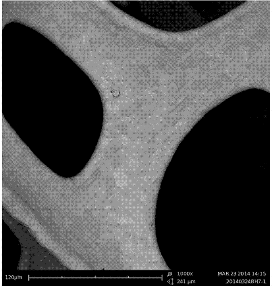
[0025] In this embodiment, Ni metal is used as an efficient catalyst for the catalytic cracking of hydrocarbon fuels. Under high temperature conditions, the Ni metal catalyst promotes the rapid cracking of hydrocarbon fuels, and carbon fibers grow on the surface; the commercialized Ni foam has a porous skeleton structure and has a large specific surface area.

specific Embodiment approach 3

[0026] Embodiment 3: The difference between this embodiment and Embodiment 1 or 2 is that the hydrocarbon fuel described in step 2 is alkanes, alcohols, ketones, benzene, natural gas, liquefied petroleum gas, biogas or coalbed methane. Other steps and parameters are the same as those in Embodiment 1 or Embodiment 2.

[0027] The main component or all components of the hydrocarbon fuel described in this embodiment have C x h y Fuel for compounds of general formula.


PUM


Abstract

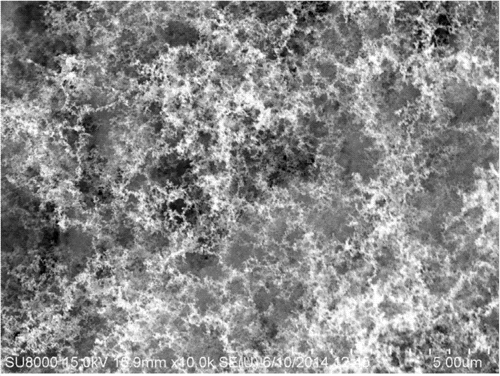
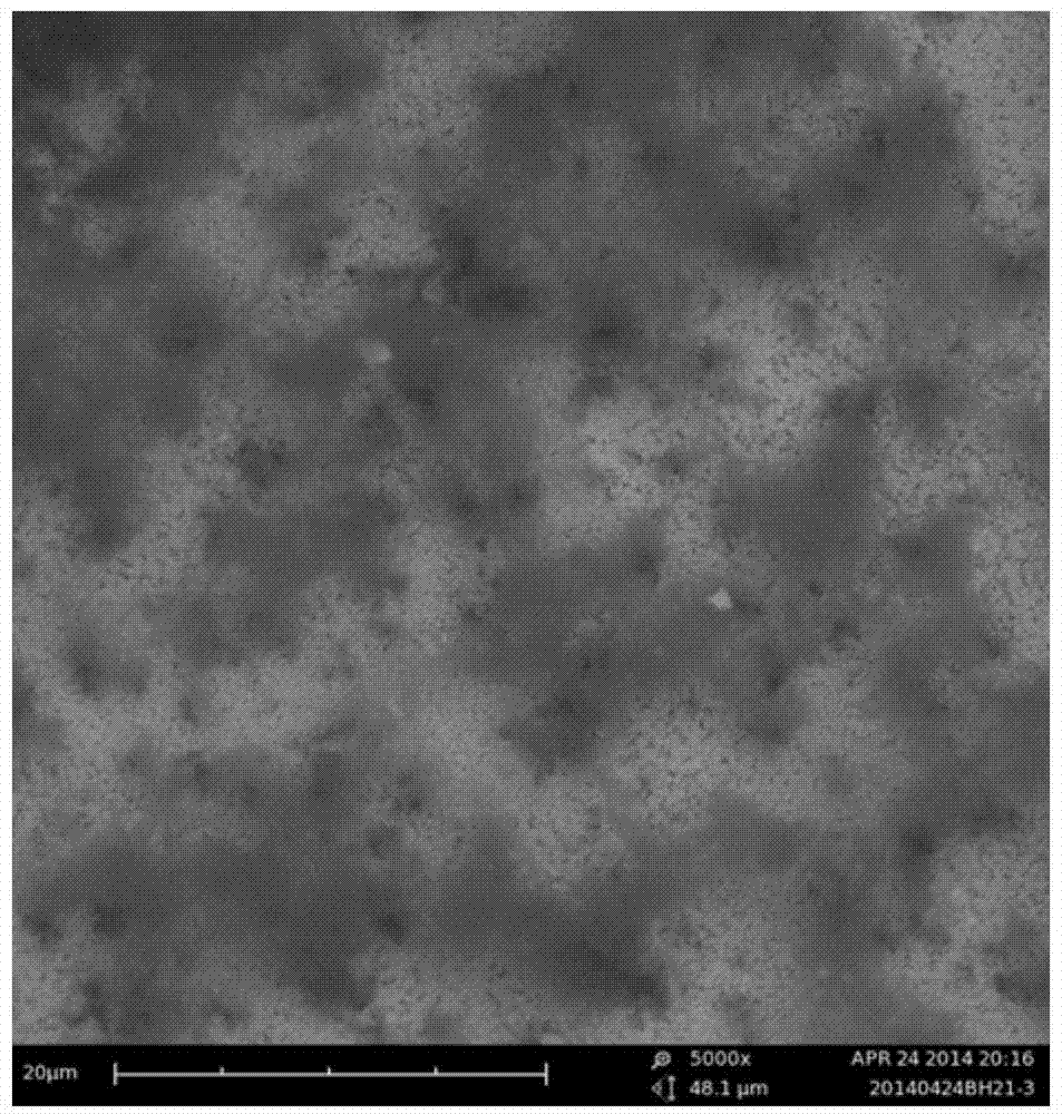
The invention discloses a method for preparing carbon fiber yarns by direct flame carbon deposition and relates to a preparation method of carbon fibers. The method aims to solve the problem that existing method for preparing carbon fibers is complex, relatively high in requirement on production equipment and relatively low in yield of product. The method for preparing the carbon fiber yarns comprises the following steps: I, shearing and moulding a catalyst, washing by anhydrous ethanol and airing to obtained the cleaned catalyst; II, connecting a hydrocarbon fuel gas tank to a combustor by virtue of a breather pipe, fixing a porous bearing part above a nozzle of a combustor, and putting the cleaned catalyst on the porous bearing part to accomplish assembly of the preparation equipment; and III, igniting the combustor, adjusting the flame temperature of the combustor, putting the catalyst on the combusting flame to be combusted and growing the carbon fiber yarns on the catalyst. According to the method disclosed by the invention, the used equipment is simple, and the catalyst is put in the hydrocarbon fuel flame, so that carbon can be quickly deposited on the surface in the flame combustion process under an open system so as to obtain a lot of carbon fibers.

Description

technical field [0001] The invention relates to a method for preparing carbon fiber, in particular to a convenient method for obtaining carbon fiber filaments by direct flame. Background technique [0002] Carbon fiber is a new type of one-dimensional carbon material. Carbon fiber has many excellent physical properties, mechanical properties and chemical stability, such as high mechanical strength and Young's modulus, good corrosion resistance, and good electrical and thermal conductivity. Therefore, received extensive attention and application. At present, there are two main methods for the preparation of carbon nanofibers: one is thermal chemical vapor deposition growth, and the other is electrospinning. The preparation of carbon nanofibers by thermal chemical vapor deposition requires the addition of metals or alloys to dissolve carbon to form metal carbides, which are used as catalysts. In addition, methane, carbon monoxide, mixed gas (H 2 / CO), acetylene or ethylene ...

Claims


Application Information

Patent Timeline
Patent Type & Authority Applications(China)
IPC IPC(8): D01F9/12
Inventor 吕静波王志红吕喆边海文张耀辉朱星宝黄喜强王丽红毋妍妍
Owner HARBIN INST OF TECH
Learn More