Organic and inorganic hybrid perovskite-based solar cell and method for manufacturing same

A solar cell and perovskite technology, applied in circuits, photovoltaic power generation, electrical components, etc., can solve the problems of difficult control of crystal quality, poor regularity, and many crystal defects, so as to improve photoelectric conversion efficiency and stability, and improve Crystal regularity and the effect of increasing the diffusion length

Active Publication Date: 2015-07-22
CHINA LUCKY FILM CORP
View PDF5 Cites 57 Cited by
  • Summary
  • Abstract
  • Description
  • Claims
  • Application Information

AI Technical Summary

Problems solved by technology

[0004] In the existing perovskite-based solar cell structure, the perovskite light-absorbing layer is generally deposited directly on the surface of the electrode modification layer (such as TiO 2 , ZnO, PEDOT:PSS and other surfaces), due to the PbI 2 and CH 3 NH 3 I rapidly self-assemble into nano-scale perovskite tiny grains during the coating process. It is difficult to control the nucleation of perovskite grains and the growth direction of the film layer. The den...

Method used


Image

  • Organic and inorganic hybrid perovskite-based solar cell and method for manufacturing same
  • Organic and inorganic hybrid perovskite-based solar cell and method for manufacturing same
  • Organic and inorganic hybrid perovskite-based solar cell and method for manufacturing same

Examples


preparation example Construction

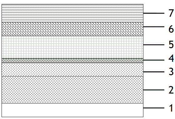
[0037] figure 1 In the organic-inorganic hybrid perovskite-based solar cell shown, before the perovskite light-absorbing layer is prepared by the liquid phase method, the surface of the electron transport layer is modified with a micro-nano structure to form an ultra-thin alignment layer. The preparation method includes the following steps :

[0038] 1) Clean the transparent electrode, etch the electrode pattern and then clean, dry, and UV / ozone treatment;

[0039] 2) preparing an electron transport layer on the transparent electrode;

[0040] 3) Perform interface modification on the surface of the electron transport layer to form an ultra-thin alignment layer;

[0041] 4) On the surface of the ultra-thin alignment layer, grow a perovskite light-absorbing layer;

[0042]5) Depositing a hole transport layer on the surface of the perovskite light-absorbing layer;

[0043] 6) Prepare a counter electrode on the hole transport layer.

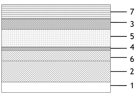
[0044] figure 2 In the organic-inorgani...

Embodiment 1

[0065] The first step is to prepare a transparent electrode:

[0066] The ITO conductive glass was etched with concentrated hydrochloric acid to form an electrode pattern, and then ultrasonically cleaned with detergent, deionized water, absolute ethanol, acetone, and isopropanol for 10 minutes, then dried with nitrogen, and treated with UV / ozone for 20 minutes.

[0067] The second step is to prepare the electron transport layer:

[0068] Coating nano-TiO on the surface of transparent electrode by screen printing method 2 The precursor solution of the particle colloid is then put into a muffle furnace for sintering at a high temperature of 450° C. for 30 minutes to form an electron transport layer with a thickness of 45 nm.

[0069] The third step is to prepare an ultra-thin alignment layer:

[0070] Uniformly dispersing the monobenzo-15-crown-5 cyclic molecular material with a mass fraction of 1% in a chloroform solvent with a mass fraction of 99% to prepare a transparent an...

Embodiment 2

[0081] Except for the third step, the preparation method of other steps is the same as that of Example 1.

[0082] The third step is to prepare an ultra-thin alignment layer:

[0083] Uniformly dispersing the tetraphenylporphyrin ring molecular material with a mass fraction of 0.5% in a dichloromethane solvent with a mass fraction of 99.5% to prepare a transparent and uniform ultra-thin alignment layer solution;

[0084] Form the above prepared solution on the surface of the electron transport layer by spin-coating to form a film with a thickness of 2nm;

[0085] The film prepared above was dried in air at 60° C. for 90 minutes to form an ultra-thin alignment layer.

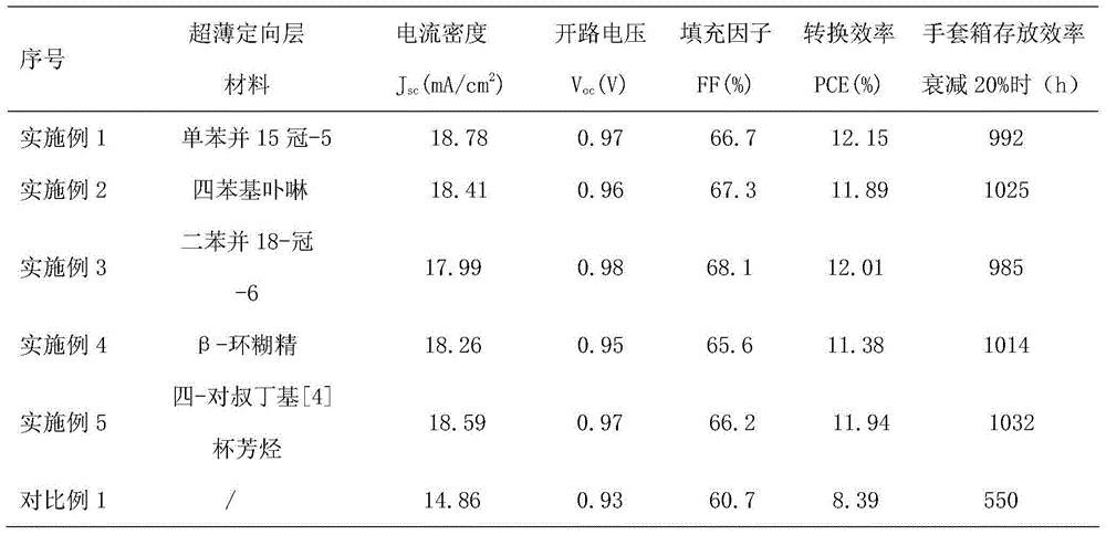
[0086] The device structure of organic-inorganic hybrid perovskite-based solar cells prepared by the above method is as follows: figure 1 Shown: G / ITO / TiO 2 / Tetraphenylporphyrin / CH 3 NH 3 PB 3 / spiro-OMeTAD / Au with an effective area of ​​0.09cm 2 , the photoelectric conversion efficiency data are shown in T...


PUM

PropertyMeasurementUnit
Thicknessaaaaaaaaaa
Thicknessaaaaaaaaaa
Thicknessaaaaaaaaaa

Abstract

The invention relates to an organic and inorganic hybrid perovskite-based solar cell and a method for manufacturing the same. The organic and inorganic hybrid perovskite-based solar cell comprises a substrate, a transparent electrode, an electron transport layer, an ultrathin orientation layer, a perovskite light absorption layer, a hole transport layer and a counter electrode. The transparent electrode, the electron transport layer, the ultrathin orientation layer, the perovskite light absorption layer, the hole transport layer and the counter electrode are sequentially stacked on the substrate. The method includes modifying micro-nano structures on the surfaces of the electron transport layer or the hole transport layer to form the ultrathin orientation layer before the perovskite light absorption layer is manufactured by the aid of a liquid phase process. The organic and inorganic hybrid perovskite-based solar cell and the method have the advantages that orientated growth of crystals of perovskite is controlled under large-ring structural effects of molecules in the ultrathin orientation layer, accordingly, the crystallization regularity can be improved, and internal defects can be reduced; the diffusion lengths of current carriers inside the perovskite light absorption layer can be effectively increased, accordingly, recombination of electron-hole pairs on the inside and interfaces of the perovskite light absorption layer can be prevented, and the photoelectric conversion efficiency and the stability of the cell can be obviously improved; the crystallization quality of the perovskite light absorption layer cannot be easily affected by film forming conditions under the orientation mold plate effects of the ultrathin orientation layer, accordingly, the device manufacturing repeatability can be improved, and the low-temperature solution method is applicable to industrially producing large-area perovskite solar cells.

Description

technical field [0001] The invention relates to the technical field of perovskite-based thin-film solar cells, in particular to an organic-inorganic hybrid perovskite-based solar cell and a preparation method thereof. Background technique [0002] Organic-inorganic hybrid perovskite-based solar cells have shown excellent optoelectronic performance and great potential in recent years. With the development of perovskite solar cell technology, the photoelectric conversion efficiency of cell devices based on this light-absorbing material is as high as 19.3%. [0003] The crystallization quality of the perovskite light-absorbing layer and its interface control with the electrode modification layer are crucial to the photoelectric performance of the battery, directly affecting the conversion efficiency and stability of the battery. The preparation methods of perovskite light-absorbing layer mainly include liquid phase method, gas phase assisted liquid phase method, gas phase co-e...

Claims


Application Information

Patent Timeline
IPC IPC(8): H01L51/42H01L51/46H01L51/48
CPCH10K30/80H10K30/00Y02E10/549
Inventor 王亚丽王金凤李秀贞刘贤豪侯丽新李丽程媛
Owner CHINA LUCKY FILM CORP
Why Eureka
Try Eureka