
Controllable vibrating electrode electric spark and electrolytic combined machining method for micro holes and vibrating system

A vibrating electrode and combined processing technology, which is applied in the direction of electric processing equipment, metal processing equipment, manufacturing tools, etc., can solve the problems of high processing accuracy and surface quality, ineffective processing of micro holes, and unsuitable processing of micro holes. , to achieve the effect of reducing the gap between electrodes, ensuring the consistency of control and processing, and high speed

Active Publication Date: 2015-09-23
NANJING UNIV OF AERONAUTICS & ASTRONAUTICS
View PDF13 Cites 36 Cited by
  • Summary
  • Abstract
  • Description
  • Claims
  • Application Information

AI Technical Summary

Problems solved by technology

[0004] On June 17, 2009, the Chinese patent with the publication number CN 101456095 A disclosed a method for accelerating the discharge of the processed material in EDM. In order to solve the problem that the processed products are not easy to be discharged in the machining of holes and deep holes, a method of ultrasonic vibration assistance is proposed while EDM machining fine deep holes, and the relative movement between the tool electrode and the workpiece is used to accelerate the discharge of products in the processing area. Improve processing quality and processing efficiency, but this method has not been applied to EDM
[0005] On March 30, 2011, the Chinese patent with the authorization number CN101693313 B disclosed a micro three-dimensional structure EDM combined milling method, with the help of layered milling The principle is to use a simple electrode for the combined processing of micro-EDM and micro-electrolytic milling to process a variety of metal alloy materials and complex cavity profiles. The CNC milling electrode does not lose the advantages of good surface quality, and achieves the beneficial effects of high machining accuracy, high speed, and low cost. However, this invention is mainly aimed at milling and is not suitable for micro-hole machining.
This invention improves the erosion efficiency and eliminates the residual stress and metamorphic layer on the processed surface, but the method has no obvious effect on the processing of micro holes, and the loss of the tube electrode is large, and the processing cost is high
[0007] On August 7, 2013, the Chinese patent with the publication number CN103231133 A disclosed a method and device for electrolysis and electric spark composite machining of non-conductive materials. The tool electrode is insulated before the non-conductive material is drilled. Under the combined action of electrochemical reaction and electrolytic spark, a layer of aluminum oxide insulating film is formed on the surface of the tool electrode. During the drilling process of the workpiece, the tool electrode The side wall remains insulated, and electrolytic spark discharge occurs only on the bottom surface where the tool electrode contacts the workpiece. Under the combined action of high temperature, impact and grinding during electrolytic spark discharge, the material is removed and the workpiece is processed. This method is mainly aimed at Composite processing of non-conductive materials cannot be applied to the processing of difficult-to-process conductive materials such as superalloys
[0015]There are a large number of small single-group hole structures in the aviation industry. Such holes often require high machining accuracy and surface quality. At present, there is still no more efficient processing method

Method used


Image

  • Controllable vibrating electrode electric spark and electrolytic combined machining method for micro holes and vibrating system
  • Controllable vibrating electrode electric spark and electrolytic combined machining method for micro holes and vibrating system
  • Controllable vibrating electrode electric spark and electrolytic combined machining method for micro holes and vibrating system

Examples


Embodiment Construction

[0038] The present invention will be further described below in conjunction with the accompanying drawings and specific embodiments.

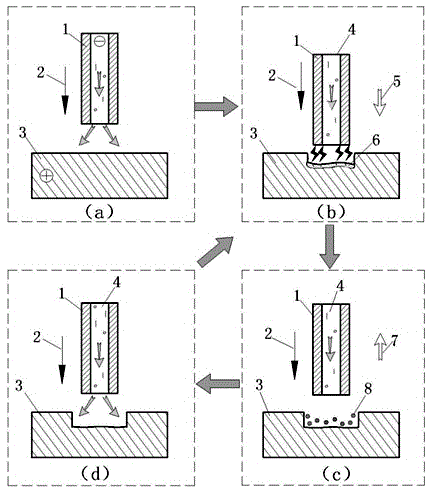
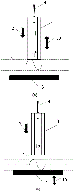
[0039] figure 1 It is the schematic diagram of the vibrating electrode EDM controllable composite machining of the present invention, in which (a) is the initial stage of processing, (b) is the stage of EDM, (c) is the stage of electrolytic processing, and (d) is the end of processing picture. It mainly includes tool electrode 1, feed direction 2, workpiece electrode 3, working fluid 4, positive vibration 5, heat-affected layer 6, negative vibration 7, and dissolved product 8. During processing, the tool electrode is connected to the negative pole, the workpiece is connected to the positive pole, and the two poles are connected to the high-frequency pulse power supply. In the working fluid circulation system, the working fluid is divided into two paths through the electromagnetic reversing valve 27, one path communicates with the inside of t...


PUM


Abstract

The invention provides a controllable vibrating electrode electric spark and electrolytic combined machining technological method and device for a single group of micro holes and belongs to the technical field of special machining. An ultralow-concentration neutral salt solution is taken as a working solution, corresponding pulse voltage is applied between the two electrodes, the electrodes vibrate in a reciprocating mode in the feeding directions of the electrodes, the gap between the two electrodes is adjusted by controlling the vibration between the electrodes, and the gap between the electrodes is made to be smaller than a spark discharge gap when the electrodes vibrate in the forward direction, so that an electric spark reaction occurs; the distance between the electrodes is larger than the discharge gap when the electrodes vibrate in the negative direction, so that spark discharge is changed into an electrolytic reaction gradually; when the distance between the electrodes is too large, the electrolytic reaction is ended, the working solution is switched to be in the deionization state, then the next machining cycle is conducted along with the feeding of the electrodes, and controllable combination of electric spark machining and electrolytic machining is achieved by optimizing the vibrating mode. By the adoption of the controllable vibrating electrode electric spark and electrolytic combined machining technological method and device, high surface quality can be obtained, and machining efficiency is improved; meanwhile, control over the machining process and machining consistency can be effectively guaranteed.

Description

technical field [0001] The invention relates to an EDM-electrolysis controllable composite processing method and a vibration system of a micro-hole vibrating electrode, belonging to the technical field of special processing. Background technique [0002] With the continuous development of the aviation industry, the design of the internal structure of the aero-engine is becoming more and more complex, and more and more micro-hole structures appear in its key components. Precision, high surface quality, and special requirements such as no burrs and sharp edges of the hole; 2) The parts materials that need to process tiny holes are generally high-strength and high-hardness difficult-to-machine materials, such as high-temperature alloys, titanium alloys, and intermetallic compounds etc.; 3) Due to the small hole diameter, the length-to-diameter ratio of micro-hole processing is often large; 4) There are special requirements for the metallographic structure of the hole wall, such...

Claims


Application Information

Patent Timeline
IPC IPC(8): B23H5/02B23H5/12B23H9/14B23H11/00
CPCB23H5/02B23H5/12B23H9/14B23H11/00
Inventor 徐正扬张彦曲宁松朱荻
Owner NANJING UNIV OF AERONAUTICS & ASTRONAUTICS
Learn More