Hydraulic structure, and base seepage condition distributed optical fiber identification system and method thereof

A distributed optical fiber, hydraulic structure technology, applied in permeability/surface area analysis, testing of machine/structural components, testing of moving fluids/granular solids, etc. problems, to achieve the effect of improving engineering application capabilities, expanding application scope, and increasing monitoring distance

Active Publication Date: 2015-10-14
HOHAI UNIV
View PDF7 Cites 22 Cited by
  • Summary
  • Abstract
  • Description
  • Claims
  • Application Information

AI Technical Summary

Problems solved by technology

[0006] The distributed optical fiber temperature sensor with integrated optical fiber Raman amplifier only amplifies and improves the analog electrical signal, but it does not fundamentally solve the problems of pulse width and signal-to-noise ratio; the distributed optical fiber Raman temperature sensor using pulse encoding technology, It is mainly aimed at single-mode fiber, and in order to improve the signal-to-noise ratio of the system and the ability to extract and distinguish signals, complex encoding and decoding techniques are required, which greatly increases the difficulty of operation and the complexity of equipment design. From its final spatial resolution In terms of the signal-to-noise ratio of the system, there are still major deficiencies; the distributed optical fiber temperature sensor using Raman correlation dual-wavelength self-calibration technology, the use of dual light sources still cannot guarantee the temperature measurement of the two channels in the same band. With the same loss, the temperature demodulation curve will still have problems such as tilt and distortion; the distributed optical fiber temperature sensor embedded in the optical switch can expand the temperature measurement optical fiber from the original one to multiple by adding an optical switch

Method used


Image

  • Hydraulic structure, and base seepage condition distributed optical fiber identification system and method thereof
  • Hydraulic structure, and base seepage condition distributed optical fiber identification system and method thereof
  • Hydraulic structure, and base seepage condition distributed optical fiber identification system and method thereof

Examples


Embodiment Construction

[0034] The present invention will be further described below in conjunction with the accompanying drawings.

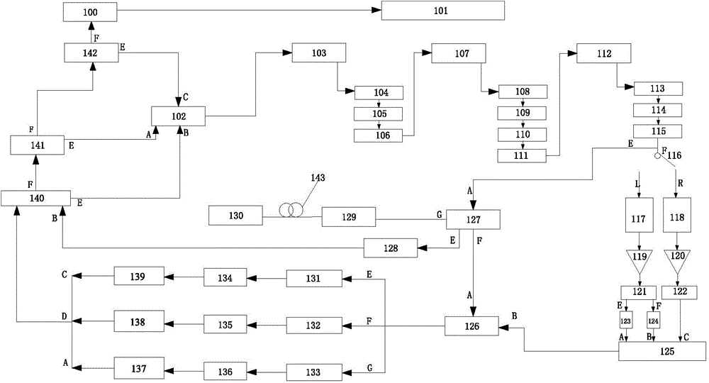
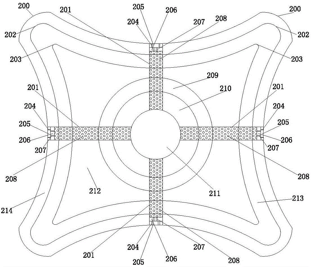
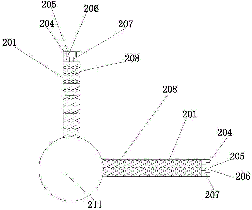
[0035] Such as Figure 1 to Figure 3 As shown, a distributed optical fiber identification system for a hydraulic structure and its foundation seepage status of the present invention includes a special single-mode optical fiber 143 for self-control heat source seepage measurement that is vertically staggered in the hydraulic structure seepage monitoring area 130, and The optical path coupler 127 and the synchronous controller 102 connected by the special single-mode optical fiber 143 for the self-control heat source measurement are provided with a monitoring thermostatic chamber 129 between the special single-mode optical fiber 143 and the optical path coupler 127 for the self-control heat source measurement. The controller 102 sequentially communicates with the mode-locked laser 103, the first wavelength division multiplexer 104, the polarization beam splitter 105, the...


PUM


Abstract

The invention discloses a hydraulic structure, and a base seepage condition distributed optical fiber identification system and a method thereof. The system comprises a specially-produced self-controlled heat source seepage single-mode optical fiber, an optical path coupler and a synchronous controller, the synchronous controller is connected with a mode locked laser, a polarization beam splitter, an isolator, a grating pair, a diffraction grating, a reflector, a beam splitter, a nonlinear crystal, a spectrometer and a Michelson interferometer, the output end of the Michelson interferometer is connected with the optical path coupler, the output end of the optical path coupler is connected with a detector and a second optical splitter respectively, the detector is connected with a digital signal processor, the second optical splitter is connected with the digital signal processor through an amplification circuit, and the digital signal processor is connected with the synchronous controller and a gatherer respectively. The system and the method have the advantages of high precision, high spatial resolution, high sensing speed, long distance monitoring, and realization of the flowing and automation of monitoring and condition identification of the hydraulic structure in bad environment and the base seepage thereof.

Description

technical field [0001] The invention relates to a hydraulic structure and its foundation seepage monitoring system and method, in particular to a hydraulic structure and its foundation seepage status distributed optical fiber identification system and method in harsh environments. Background technique [0002] Seepage is an important factor related to the safe and long-term service of hydraulic structures, especially for earth-rock granular structures such as earth-rock dams and embankments, the problem of seepage and its impact are more prominent. It is of great significance to ensure the safety of the project to develop advanced, practical and reliable seepage measurement equipment for wading structures, strengthen its rational layout and efficient transmission and scientific processing and analysis of monitoring data, so as to accurately identify the seepage status of structures. With the rapid development of optical fiber sensing technology and the continuous expansion o...

Claims


Application Information

Patent Timeline
IPC IPC(8): G01N15/08
CPCG01K11/32G01M3/047G01K11/324G01K11/00B23P19/04G01N21/21G01N21/85G01N21/88
Inventor 苏怀智杨孟
Owner HOHAI UNIV
Why Eureka
Try Eureka