Combination of cylinder bore and piston ring

A technology of piston rings and cylinder holes, applied in the directions of piston rings, cylinders, cylinder heads, etc., can solve a large number of precision processes, impracticality and other problems, and achieve the effects of excellent wear resistance, small area ratio and small friction loss.

Inactive Publication Date: 2016-05-04
RIKEN CO LTD +1
View PDF8 Cites 8 Cited by
  • Summary
  • Abstract
  • Description
  • Claims
  • Application Information

AI Technical Summary

Problems solved by technology

However, it is not practical to form the sliding surface with the above-mentioned structure by precisely controlling the depth of the concave portion, etc., which requires a large number of precise processes.

Method used


Image

  • Combination of cylinder bore and piston ring
  • Combination of cylinder bore and piston ring
  • Combination of cylinder bore and piston ring

Examples


Embodiment 1~4 and comparative example 1~2

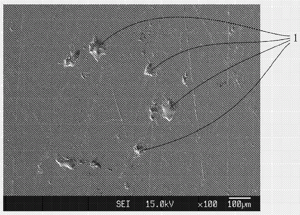
[0031] Sand blasting is performed on one side of a JISADC12 aluminum alloy plate (70mm×100mm×10mm) equivalent to the cylinder bore, and the mass % is C: 0.3%, Si: 0.2%, Mn: 0.3%, Cr: 0.5%, A wire composed of Mo: 0.2%, the rest of Fe and unavoidable impurities is used as a thermal spraying material, and an iron-based thermal spraying film of about 500 μm is formed by an arc thermal spraying method. The iron-based thermal sprayed coatings of Examples 1 to 4 and Comparative Examples 1 to 2 were basically formed under the same thermal spraying conditions, but were polished in the 70 mm width direction so that the surface properties (Rpk value) were different. Next, the piston ring (equivalent to SUS420J2 subjected to nitriding treatment, nominal diameter (d) 90 mm, width (h1) 1.2 mm, thickness (a1) 3.2 mm) forms a hard carbon film of about 1 μm on the outer peripheral surface. Since the hard carbon films of Examples 1 to 4 and Comparative Examples 1 to 2 had Rpk of 0.2 to 0.3 μm ...

Embodiment 5~7

[0049] Aluminum alloy plates corresponding to the cylinder bores of Examples 5 to 7 were produced in the same manner as in Example 1 except that the thermal spraying conditions of the iron-based thermal sprayed coating were changed so as to vary the area ratio of the minute pits. In addition, a hard carbon film having the same properties as in Example 1 was used for a piston ring combined with these aluminum alloy plates. The Rpk value and micro-crater area ratio of the iron-based thermal sprayed coatings of Examples 5-7 were measured similarly to Example 1, and the abrasion test and abrasion test were also performed similarly to Example 1.

Embodiment 8

[0051] The material of the piston ring is SUS440B equivalent material, and a CrN film base layer with a film thickness of about 30 μm is formed on it, and a metal Cr intermediate layer of about 0.5 μm and a hard carbon film of about 1.5 μm are formed by vacuum arc ion plating. Other than that, the piston ring of Example 8 was produced in the same manner as in Example 1. As a result of measuring the Rpk value, hydrogen content, and Martens hardness of the hard carbon film, the Rpk value was 0.14 μm, the hydrogen content was 0.7 atomic %, and the Martens hardness was 24.1 GPa. In addition, as an aluminum alloy plate combined with the piston ring of Example 8, an iron-based thermal sprayed coating having the same properties as in Example 1 was used, and an abrasion test and an abrasion test were performed.


PUM

PropertyMeasurementUnit
thicknessaaaaaaaaaa
hardnessaaaaaaaaaa
thicknessaaaaaaaaaa

Abstract

In order to provide a combination of a cylinder bore and a piston ring using a cylinder bore spraying technique that can utilize an aluminum alloy cast made by normal die casting, and that has exceptional scuffing resistance and abrasion resistance and low friction loss even in severe sliding conditions with an engine subjected to a high load, an iron-based sprayed film formed on a face of a cylinder bore of an internal combustion engine that slides against a piston ring is combined with a hard carbon film formed on an outer peripheral sliding face of the piston ring, the iron-based sprayed film having an Rpk value in a surface roughness curve of less than 0.20 [mu]m, and the hard carbon film having an Rpk value in a surface roughness curve of less than 0.15 [mu]m.

Description

technical field [0001] The invention relates to a combination of a cylinder bore of an internal combustion engine and a piston ring that slides relative to the inner peripheral surface of the cylinder bore, in particular to a cylinder bore with an iron-based thermal spray coating formed on the inner peripheral sliding surface and on the outer peripheral sliding surface A combination of piston rings formed with a hard carbon film. Background technique [0002] In recent years, there has been a strong demand for improvement in fuel efficiency of internal combustion engines, mainly automobile engines. Therefore, research and development of components aimed at miniaturization, weight reduction, frictional loss reduction, and the like are extensively carried out. For example, try to use an aluminum metal alloy with a small specific gravity (hereinafter referred to as "aluminum alloy") for the cylinder and coat a hard carbon film with a low coefficient of friction (also called "D...

Claims


Application Information

Patent Timeline
Patent Type & Authority Applications(China)
IPC IPC(8): C23C4/06F02F1/18C23C4/131
CPCC23C4/06F05C2253/12C23C4/131C23C4/18C23C14/0605C23C14/5886F02F1/18F02F1/00C23C14/325F16J9/12F16J9/26
Inventor 篠原章郎诸贯正树
Owner RIKEN CO LTD
Why Eureka
Try Eureka