Composition and delivery system
A technology of a delivery system and a composition, which is applied in the field of delivering reagents to the subject's target in the delivery system of a stent, can solve problems such as hindering development, and achieve the effect of avoiding release distribution
- Summary
- Abstract
- Description
- Claims
- Application Information
AI Technical Summary
Problems solved by technology
Method used
Image
Examples
Embodiment 1
[0134] Example 1: Melt entrapment of microparticles within thermoset PLGA / PEG particles
[0135] 1. Preparation of PLGA / PEG sheet:
[0136] 1.1 Weigh out 2.5 g of PLGA / PEG particles (<100 micron in size and containing 6.5% w / w or 8% w / w of 400 Da PEG) into a weighboat.
[0137] 1.2 Weigh 0.278 g (i.e. 10% w / w of the total combined mass) of PLGA "placebo" particles (20-50 micron diameter spherical particles) in a separate weighing boat, after which PLGA / PEG particles are added and wiped with a wipe. Knife to mix well.
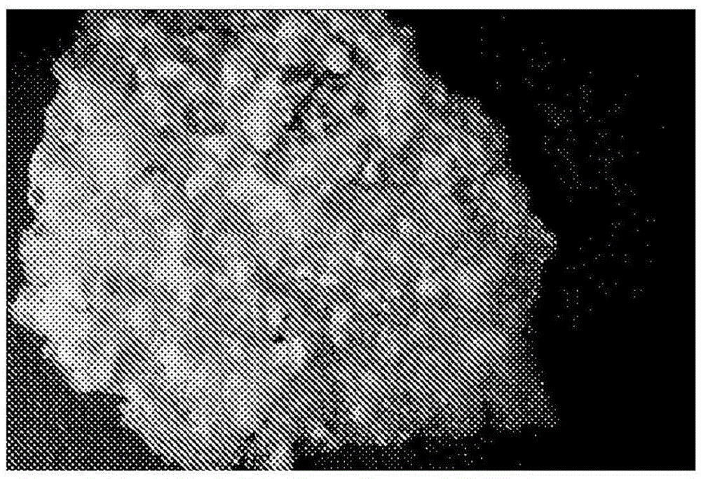
[0138] 1.3 Pour the contents of the weighing boat onto the PTFE sheet and flatten with a spatula to a continuous granular layer of approximately 2mm depth (Figure 1).
[0139] 1.4 Put the PTFE sheet into an oven at 50°C for about 6 hours. Transparent flakes of PLGA / PEG will form.
[0140] 2. Preparation of thermosetting PLGA / PEG blend particles containing placebo particles
[0141] 2.1 Cut the polymer sheet into pieces smaller than 2 x 2 cm using scissors. ...
Embodiment 2
[0148] Example 2. Reduction of Cmax: Release Studies
[0149] Comparison of drug-loaded PLGA microparticle formulations:
[0150] This example shows a comparison of microparticles (MP) with MP trapped in the scaffold of PLGA / PEG particles versus particles made by melt blending MP into PLGA / PEG.
[0151] For better controlled drug release by reducing the initial "burst" effect inherent in polymer controlled release systems, model actives are incorporated into the stent. Burst release can be significantly reduced by a formulation strategy using prednisolone-loaded polymer microspheres incorporated in the scaffold as shown.
[0152] method:
[0153] Prednisolone-bound PLGA particles were manufactured using the following solid dispersion emulsion method:
[0154] A 1 liter batch of a solution of 0.3% (w / v) PVA in distilled water was completely dissolved overnight on a magnetic stirrer set at about 200 rpm. Prior to use, the PVA solution was passed through a 0.2 micron filt...
Embodiment 3
[0168] Embodiment 3: Release (mwt408, logP6.85) of oil red-O as model lipophilic drug
[0169] Purpose:
[0170] To determine the release profile over time of microparticles (MPs) from oil red-O (ORO) loading and compare the release rates of small (20-30 micron) MPs with larger (50-100 micron) MPs.
[0171] It was also to determine if incorporation into PLGA / PEG scaffolds would reduce burst release and provide more sustained release over time.
[0172] method:
[0173] The PLGA / PEG blend used was made by incorporating 8% of PEG400 into PLGA85:15 (LP671). PLGA microparticles were prepared using the DCM emulsion method and using 1% ORO loading in the microparticles. Each 50 mg granule therefore contains a maximum of 500 mg of drug.
[0174] Bracket Manufacturing:
[0175] 300 mg of PLGA / 8% PEG particles in the 100-200 micron size fraction were weighed into a weighing boat and 100 mg of OROMP was added and mixed by hand.
[0176] 320ml of liquid carrier (1% pluronics ...
PUM
| Property | Measurement | Unit |
|---|---|---|
| Glass transition temperature | aaaaa | aaaaa |
| Size | aaaaa | aaaaa |
| Size | aaaaa | aaaaa |
Abstract
Description
Claims
Application Information
 - R&D
- Intellectual Property
- Life Sciences
- Materials
- Tech Scout
- Unparalleled Data Quality
- Higher Quality Content
- 60% Fewer Hallucinations
Browse by: Latest US Patents, China's latest patents, Technical Efficacy Thesaurus, Application Domain, Technology Topic, Popular Technical Reports.
© 2025 PatSnap. All rights reserved.Legal|Privacy policy|Modern Slavery Act Transparency Statement|Sitemap|About US| Contact US: help@patsnap.com


