Porous silicon-carbon composite material and preparation method and application thereof

A carbon composite material and composite material technology, applied in the field of porous silicon-carbon composite material and its preparation, can solve the problems of difficult industrialization, high equipment requirements, high cost, etc., achieve short transmission distance and alleviate volume expansion effect , the effect of improving conductivity

Active Publication Date: 2016-08-03
ZHEJIANG UNIV
View PDF4 Cites 30 Cited by
  • Summary
  • Abstract
  • Description
  • Claims
  • Application Information

AI Technical Summary

Problems solved by technology

However, the method of CVD to deposit silicon particles in carbon nanotubes has very high requirements on equipment

Method used


Image

  • Porous silicon-carbon composite material and preparation method and application thereof
  • Porous silicon-carbon composite material and preparation method and application thereof
  • Porous silicon-carbon composite material and preparation method and application thereof

Examples


Embodiment 1

[0030] 1) Heat-treat magnesium silicide at 700°C for 20 hours, and pass excess CO 2 80% CO by volume 2 / Ar mixed gas as the reaction gas.

[0031] 2) The product obtained in step 1) was treated for 10 hours in a certain concentration of hydrochloric acid solution, wherein the concentration of hydrochloric acid was 0.5 mol / liter, after the acid treatment, it was washed 5 times with deionized water, then centrifuged, and finally vacuum-dried.

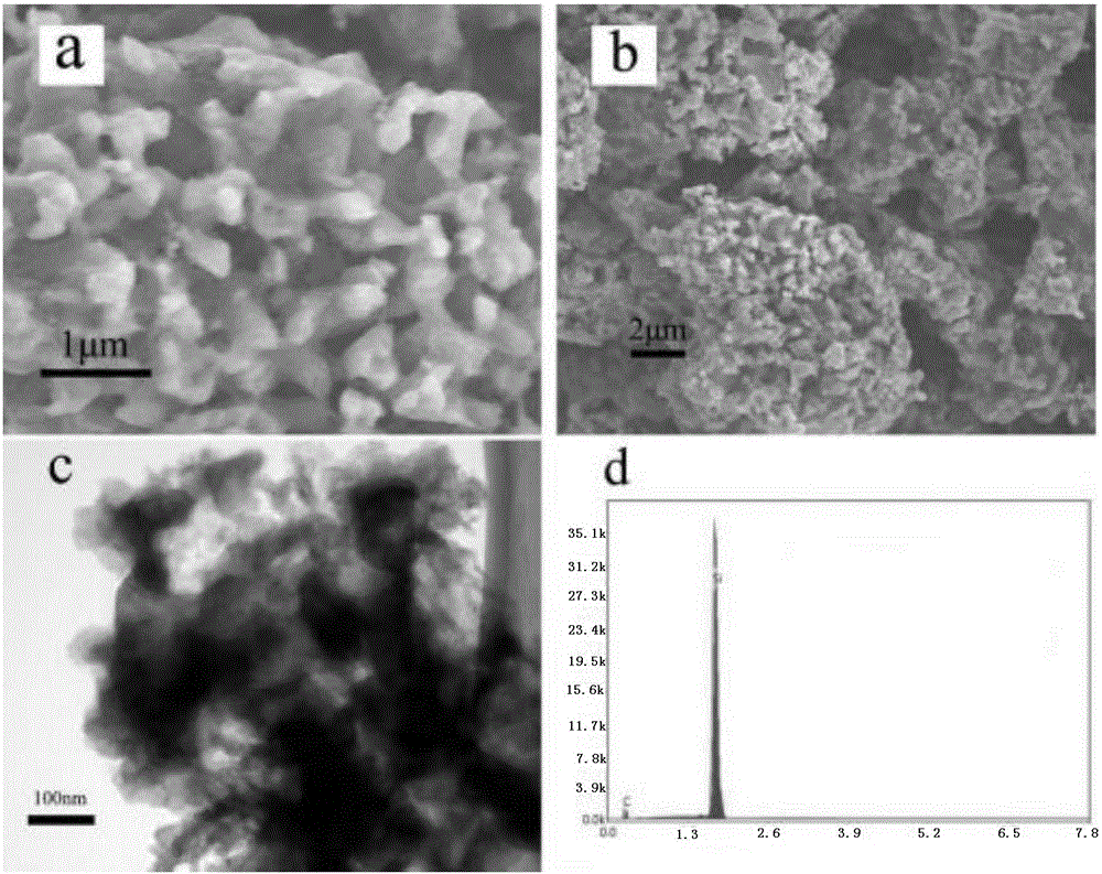
[0032] The relevant characterization results of the porous silicon-carbon composite material prepared in this example are as follows figure 1 shown. It can be seen from the figure that the product of this example is a porous structure with a large number of uniformly distributed nanoscale pores, the mass fraction of carbon is about 40%, and it is uniformly coated on the surface of silicon in the form of an amorphous carbon film, forming a porous structure with a core. -Silicon-carbon composite material with shell structure characterist...

Embodiment 2

[0036] The preparation process is exactly the same as in Example 1, the difference is only that CO 2 / Ar mixture, CO 2 The volume fraction is 60%. The morphology of the prepared porous silicon-carbon composite material is similar to that of Example 1, but the mass fraction of carbon is about 45%.

Embodiment 3

[0038] 1) Heat-treat magnesium silicide at 800°C for 15 hours, and pass excess CO 2 50% CO by volume 2 / Ar mixed gas as the reaction gas.

[0039] 2) The product obtained in step 1) was treated for 5 hours in a certain concentration of hydrochloric acid solution, wherein the concentration of hydrochloric acid was 2.0 mol / liter, after the acid treatment, it was washed 7 times with deionized water, then centrifuged, and finally vacuum-dried.

[0040] The morphology of the porous silicon-carbon composite material prepared in this example is similar to that of Example 1, but the mass fraction of carbon is about 46%.

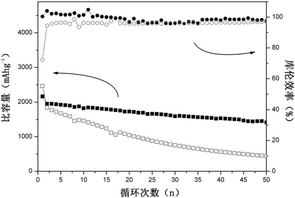
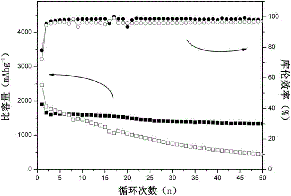
[0041] The porous silicon-carbon composite material prepared in this example was made into a button battery for performance testing, and the cycle specific capacity and Coulombic efficiency were compared with the porous silicon-carbon composite material prepared in the comparative example, as shown in image 3 shown. It can be seen from the figure that after 50 cy...


PUM


Abstract

The invention discloses a preparation method of a porous silicon-carbon composite material.The preparation method specifically comprises the steps that magnesium silicide powder is placed in a CO2-Ar mixed atmosphere to be subjected to heat treatment at the temperature of 700 DEG C-900 DEG C and then subjected to acid pickling and aftertreatment to obtain the porous silicon-carbon composite material, wherein the volume fraction of CO2 in the CO2-Ar mixed atmosphere is 10%-90%.According to the preparation method, the technology is simple, repetition is easy to achieve, and large-scale industrialized production can be achieved.When the porous silicon-carbon composite material prepared through the method is applied to a lithium ion battery by serving as a negative electrode material, the circulating stability of the lithium ion battery can be significantly improved.

Description

technical field [0001] The invention belongs to the field of preparation of composite materials, and in particular relates to a porous silicon-carbon composite material and its preparation method and application. Background technique [0002] Lithium-ion battery is a rechargeable battery widely used in modern society. Since lithium has an extremely low specific gravity among all metals and has the most negative electrode potential, when lithium is used as a battery material, it will have significant advantages such as high energy density and high charging voltage. However, when lithium is used as a battery negative electrode material, it will produce dendrite segregation during the process of lithium precipitation, forming dendritic lithium dendrites, which will gradually grow to pierce the separator and connect the positive and negative electrodes. Make the battery short circuit, dangerous. Therefore, today's industrialized lithium battery anode material is not metallic l...

Claims


Application Information

Patent Timeline
IPC IPC(8): H01M4/36H01M4/38H01M4/583H01M10/0525
CPCH01M4/364H01M4/386H01M4/583H01M10/0525Y02E60/10
Inventor 杜宁张亚光张辉杨德仁
Owner ZHEJIANG UNIV
Why Eureka
Try Eureka