Denitration system and denitration processing method of plasma synergistic catalyst

A plasma and treatment method technology, applied in the field of environmental protection, can solve the problems of deactivation, high discharge energy consumption, catalyst clogging, etc., and achieve the effects of improving life, reducing NO2 generation, and avoiding erosion and clogging

Inactive Publication Date: 2016-08-10
CHINA UNIV OF PETROLEUM (BEIJING) +2
View PDF13 Cites 10 Cited by
  • Summary
  • Abstract
  • Description
  • Claims
  • Application Information

AI Technical Summary

Problems solved by technology

[0004] In view of the technical problem of high energy consumption of low-temperature plasma discharge in the prior art, and the shortcomings of the current high-dust arrangement of commercial SCR catalysts that easily lead to catalyst clogging and deactivation, ...

Method used


Image

  • Denitration system and denitration processing method of plasma synergistic catalyst
  • Denitration system and denitration processing method of plasma synergistic catalyst
  • Denitration system and denitration processing method of plasma synergistic catalyst

Examples


Embodiment 1

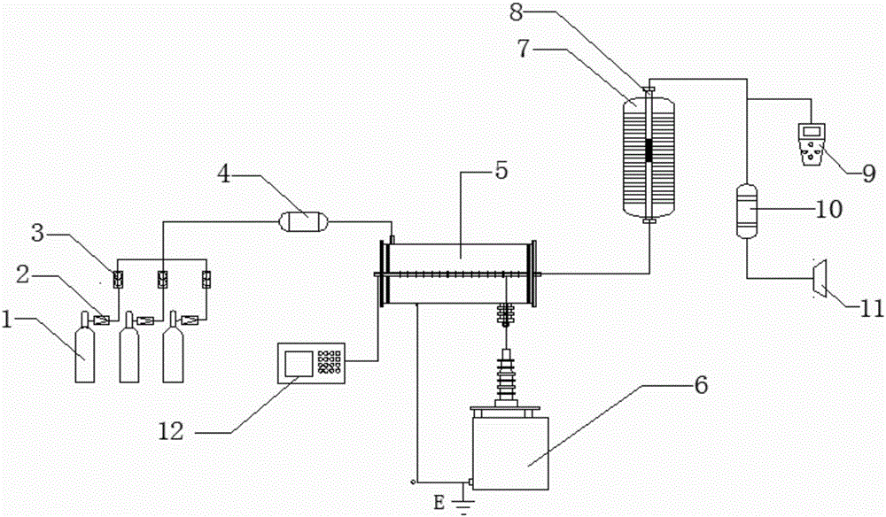
[0058] Such as figure 1 As shown, this embodiment provides a denitrification system with plasma co-catalyst, which includes a gas mixing system, a plasma reaction system, a fixed bed catalytic reactor 8, an absorption device 10 and an air induction device 11 connected in sequence. The plasma reaction system includes a plasma reactor 5 and a discharge power supply 6 ; an oscilloscope 12 is arranged between the plasma reactor 5 and the discharge power supply 6 .

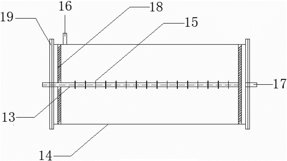
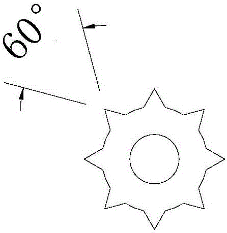
[0059] The plasma reactor 5 is a line-barrel structure, such as figure 2 As shown, it includes a center electrode 13 and a ground electrode 14, and the ground electrode 14 surrounds the center electrode 13 in a cylindrical shape; the center electrode 13 is connected to the positive pole of the discharge power supply 6, and the ground electrode 14 is connected to the ground electrode of the discharge power supply 6, and the center electrode 13 The discharge gap with the grounding electrode 14 is 18.5mm; the center ele...

Embodiment 2

[0069] In this embodiment, except that the oxygen volume content in the flue gas to be treated prepared in step (1) is 5%, the structure and layout of other devices, and the treatment process are all the same as in Example 1, and the nitrogen oxides are detected after the reaction. The removal rate is 94.21%.

Embodiment 3

[0071] In this embodiment, except that the oxygen volume content in the flue gas to be treated prepared in step (1) is 7%, the structure and layout of other devices, and the treatment process are all the same as in Example 1, and the concentration of nitrogen oxides is detected after the reaction. The removal rate is 96.33%.


PUM

PropertyMeasurementUnit
Lengthaaaaaaaaaa
The inside diameter ofaaaaaaaaaa
Lengthaaaaaaaaaa

Abstract

The invention provides a denitration system and denitration processing method of a plasma synergistic catalyst. The system includes a gas mixing system, a plasma reaction system, a fixed-bed catalytic reactor, an absorbing device, and an induced draft device, which are connected in sequence. The method comprises: introducing mixed to-be-processed flue gas and ammonia gas into a plasma reactor, performing streamer discharge under the action of high voltage to generate active substances, such as electrons, ions, and free radicals, and performing primary denitration; mixing the flue gas subjected to primary denitration with ammonia gas under the catalytic action of a catalyst, and reacting NOx in flue gas with ammonia gas to achieve denitration; and discharging tail gas after absorption. A synergistic effect between streamer discharge plasma and the low-temperature catalyst is utilized to remove nitric oxide from flue gas at a low temperature with low energy consumption. The inhibition of oxygen on nitric oxide removal is overcome, low-dust arrangement or tail arrangement of an SCR device is realized, and the life of the catalyst is prolonged.

Description

technical field [0001] The invention belongs to the technical field of environmental protection, and relates to a denitrification system and a treatment method thereof with a plasma co-catalyst, in particular to a denitrification system using a streamer discharge plasma co-catalyst and a treatment method thereof. Background technique [0002] Nitrogen oxides are a common pollutant in the atmosphere, which has a great impact on the environment, including the formation of smog, acid rain, photochemical smog, and the destruction of the ozone layer. Industry (especially coal-fired power plants) emits the vast majority of NOx emissions. At present, the widely used flue gas denitrification technology at home and abroad is selective catalytic reduction (SCR), which generally uses vanadium-titanium catalysts. High-dust arrangements are generally adopted, and the SCR device is placed before the electrostatic precipitator, so that the washing of a large amount of fly ash and dust in ...

Claims


Application Information

Patent Timeline
IPC IPC(8): B01D53/86B01D53/56B01D53/32
CPCB01D53/32B01D53/8625B01D2259/818
Inventor 浦鹏刘啸周红军
Owner CHINA UNIV OF PETROLEUM (BEIJING)
Why Eureka
Try Eureka