Method for preparing modified ceramic mold shell through special-shaped cross section short carbon fibers

A technology of chopped carbon fiber and special-shaped cross-section, which is applied in the field of preparation of special-shaped cross-section chopped carbon fiber modified ceramic formwork, which can solve the problem of thermal resistance of thick formwork, high axial strength and modulus, high cost of carbon fiber cloth, etc. problem, to achieve the effect of little change in the original process flow, strong anti-pullout ability, and good enhancement effect

Active Publication Date: 2016-08-10
JIANGSU UNIV +1
View PDF7 Cites 16 Cited by
  • Summary
  • Abstract
  • Description
  • Claims
  • Application Information

AI Technical Summary

Problems solved by technology

[0003] The axial strength and modulus of carbon fiber are high, the specific heat is between non-metal and metal, and the performance is stable. It is suitable for applying it to the preparation of formwork to improve the strength and heat dissipation performance; Chinese Patent Document No. CN103252448A records "a kind of "Preparation method of thin-walled high-strength formwork for single crystal blades", this method is to use continuous carbon fiber cloth to cover the baked formwork to increase the strength. Although this method has a certain strengthening effect, it can only strengthen the surface of the formwork. The heat dissipation ability cannot

Method used


Image

  • Method for preparing modified ceramic mold shell through special-shaped cross section short carbon fibers
  • Method for preparing modified ceramic mold shell through special-shaped cross section short carbon fibers
  • Method for preparing modified ceramic mold shell through special-shaped cross section short carbon fibers

Examples


Embodiment Construction

[0029] The present invention is further described in detail with the given examples below, so as to completely and accurately understand the characteristics of the present invention.

[0030] The following is a specific embodiment given by the inventor.

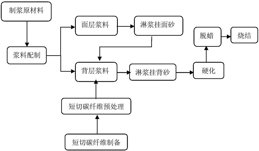
[0031] The invention discloses a method for making a modified ceramic mold shell with a special-shaped cross-section chopped carbon fiber, comprising the following steps:

[0032] (1) Two barrels of slurry, A and B, are prepared, of which barrel A is the slurry for the surface layer and transition layer, barrel B is the slurry for the back layer, and the mass ratio of corundum powder to silica sol in barrel A is 3:1, and the corundum The powder is 320 mesh; the mass ratio of corundum powder and silica sol in the B barrel slurry is 2:1, and the mass ratio of corundum powder 320 mesh to 200 mesh is 4:1.

[0033] (2) Open A and B mixing tanks (L type), pour silica sol, add wetting agent and defoamer of 0.1% of the mass of silic...


PUM

PropertyMeasurementUnit
Lengthaaaaaaaaaa

Abstract

The invention relates to the field of precision casting of high-temperature alloy vacuum furnaces, in particular to a method for preparing a modified ceramic mold shell through special-shaped cross section short carbon fibers. The mold shell is a compound shell and comprises a surface layer and a back layer modified by adding the special-shaped cross section short carbon fibers. The method comprises the preparation steps that surface layer slurry and back layer slurry are prepared correspondingly; the short carbon fibers which are evenly scattered in advance are added into the back layer slurry; the surface layer is coated with the surface layer slurry, the back layer is coated with the back layer slurry, and sand is sprayed to the surface layer and the back layer; the slurry coating and sand spraying operations are conducted repeatedly till a preset number of layers is met; the surface layer slurry is used for slurry sealing, and the mold shell is dewaxed; and the mold shell is cooled in a furnace after being roasted. According to the mold shell prepared through the method, the fibers are scattered evenly and are not likely to be pulled out and lose efficacy, the strength of the mold shell is improved, the thickness of the mold shell is reduced, the heat dissipation performance of the mold shell is enhanced, the performance requirements for thin walls and high strength are met, and the yield of single-crystal blades is increased.

Description

technical field [0001] The invention relates to the field of high-temperature alloy vacuum furnace precision casting, in particular to a method for preparing a modified ceramic mold shell with special-shaped cross-section chopped carbon fiber. Background technique [0002] The preparation of superalloy columnar crystal / single crystal structure by directional solidification technology is a key technology in the manufacture of aeroengine turbine blades and gas turbine blades; in order to obtain high-quality superalloy blades, ceramic shells are required to have sufficient strength and excellent heat dissipation performance. The commonly used formwork strengthening method in production is to increase the number of formwork layers, but this method is obviously contrary to the technical requirements of increasing the temperature gradient by reducing the formwork thickness in the directional solidification process. [0003] The axial strength and modulus of carbon fiber are high, ...

Claims


Application Information

Patent Timeline
IPC IPC(8): B22C9/04
CPCB22C9/04
Inventor 赵玉涛张弛马德新贾志宏梁向锋张钊谢道存
Owner JIANGSU UNIV
Why Eureka
Try Eureka