Short wave optical thermal detector and focal plane array device thereof

A thermal detector and photothermal detection technology, applied in the field of photoelectric detectors, can solve the problems of no application, poor detection rate and response time, low electromagnetic radiation absorption, etc., to achieve strong versatility, fast response speed, and low thermal mass. Effect

Active Publication Date: 2016-09-28
WUHAN IND INST FOR OPTOELECTRONICS
View PDF3 Cites 14 Cited by
  • Summary
  • Abstract
  • Description
  • Claims
  • Application Information

AI Technical Summary

Problems solved by technology

[0003] As mentioned above, the short-wave optical detectors used in the ultraviolet, visible and near-infrared bands are mainly photon detectors, while the photothermal detectors have low detection rate and response time due to their low absorption of electromagnetic radiation in the short-wave optical band. are much worse than known photon-type detectors and are therefore hardly used

Method used


Image

  • Short wave optical thermal detector and focal plane array device thereof
  • Short wave optical thermal detector and focal plane array device thereof
  • Short wave optical thermal detector and focal plane array device thereof

Examples


Embodiment 1

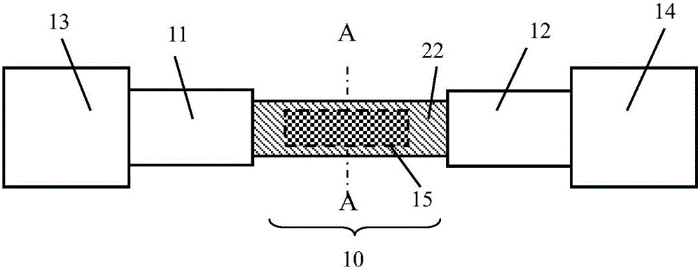
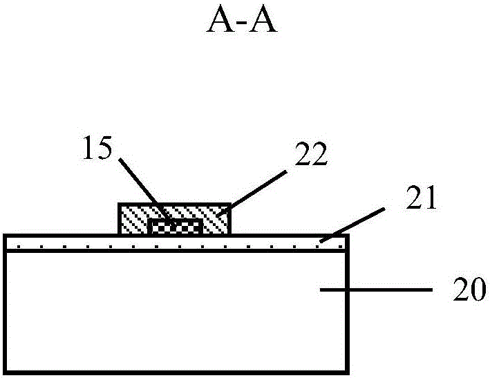
[0023] Such as figure 1 and figure 2 As shown, the short-wave optical thermal detector in this embodiment includes a photothermal detection structure 10, two electrodes 11, 12, two electrical contacts or metal pads 13 and 14, and a silicon substrate 20, wherein the two electrodes 11, Both ends of 12 are respectively connected to photothermal detection structure 10 and electrical contact points or metal pads 13 and 14 . The photothermal detection structure 10 is at least composed of heat-sensitive wires 22 and conductive nanoparticles 15 , and an insulating medium layer 21 is placed between the heat-sensitive wires 22 and the substrate 20 . Electrical contacts or metal pads 13 and 14 are interconnected with readout circuitry on substrate 20 or external circuitry (not shown). The insulating dielectric layer 21 is preferably silicon dioxide.

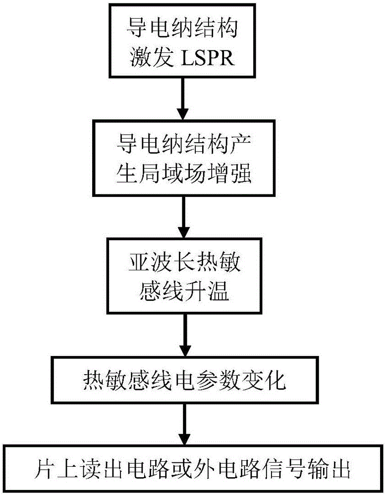
[0024] The operating principle of the short-wave optical thermal detector in this embodiment is as follows: image 3 As shown, the in...

Embodiment 2

[0031] In order to further improve the absorption efficiency and reduce the loss of light energy caused by the scattering of nanoparticles, such as Figure 6 As shown, the present invention also provides a preferred embodiment of a short-wave optical thermal detector. The difference between this embodiment and Embodiment 1 is that: the conductive nanoparticle 15 is embedded in the heat sensitive wire 22, and the heat sensitive wire 22 A metal reflective layer 25 is added below, and there is an insulating medium layer 21 with low thermal conductivity between the metal reflective layer 25 and the heat-sensitive wire 22, and the material of the insulating medium layer 21 is preferably silicon dioxide. In addition, the surface of the heat sensitive line 22 also contains a passivation protection layer 23 . The improved structure reflects the incident or scattered electromagnetic radiation reaching the reflective layer back to the photothermal detection structure, which can enhance ...

Embodiment 3

[0033] The further improvement of this embodiment relative to Embodiment 2 is that there is a cavity 26 and a metal reflective layer 25 etched by the isolation layer 27 under the photothermal detection structure, such as Figure 7 shown. The cavity 26 is used to block the thermal conduction loss of the thermal detection structure through the substrate below it, and plays a role of thermal isolation. At the same time, when its height meets a quarter of the detection wavelength, it will also form resonance absorption, which can significantly enhance the wavelength. nearby absorptivity. The material used for the isolation layer 27 can be selected from inorganic media such as silicon oxide, silicon nitride or organic polymers such as polyimide or BCB. The medium of the cavity 26 is inert gas or vacuum. In this embodiment, the insulating dielectric layer 21 is located between the isolation layer 27 and the heat sensitive wire 22 .

[0034] Investigate the thermal conductance and...


PUM


Abstract

The invention discloses a short wave optical thermal detector and a focal plane array device thereof. The short wave optical thermal detector includes an electrode, an electric contact, a photo-thermal detection structure and a substrate. Two ends of the electrode are connected with the electric contact and the photo-thermal detection structure respectively. The photo-thermal detection structure includes heat reactive lines and conducting Na particles capable of generating local surface Plasmon resonance. When electromagnetic radiation of a specific wavelength acts on the conducting Na particles, local surface Plasmon resonance is generated, os that hot spots are formed. Therefore, temperature rise of the heat reactive lines is caused and electric parameter change is caused, and detection of specific electromagnetic radiation by the detector is realized. Through adjusting geometric parameters of the conducting Na particles and combining the conducting Na particles of different parameters, selective spectrum radiation detection and multi-waveband radiation detection are realized. The optical thermal detector provided by the invention is simple in structure and the low cost short wave optical (ultraviolet, visible light and near infrared) waveband detector and the focal plane array device thereof are realized.

Description

technical field [0001] The invention relates to photoelectric detector technology, specifically a photothermal detector and its focal plane array, which are used to detect electromagnetic radiation in short-wave optical bands (ultraviolet, visible light and near-infrared). Background technique [0002] The physical effects of photodetectors are usually divided into photon effects and photothermal effects, and the corresponding detectors are called photon detectors and photothermal detectors, respectively. The common feature of various photon-type detectors is the use of semiconductor energy band materials. The photon energy has a direct effect on the generation of photoelectrons in the detection material. Therefore, photon-type detectors have a cut-off response frequency or wavelength, and the spectral response is limited to a certain band. Therefore Different material systems determine that detectors have different response wavelength ranges, which are generally difficult t...

Claims


Application Information

Patent Timeline
Patent Type & Authority Applications(China)
IPC IPC(8): H01L31/09H01L27/146
CPCH01L27/14665H01L31/09
Inventor 赖建军
Owner WUHAN IND INST FOR OPTOELECTRONICS
Why Eureka
Try Eureka