Quantum-dot light-emitting diode and preparation method therefor

A quantum dot light-emitting and diode technology, which is applied in semiconductor/solid-state device manufacturing, electrical components, electric solid-state devices, etc., can solve the problems of unbalanced carrier transport rate, unbalanced hole and electron, high electron injection rate, etc. , to achieve the effects of reducing assembly cost, good solubility, and increasing the chance of compounding

Inactive Publication Date: 2016-11-09
DONGHUA UNIV
View PDF4 Cites 19 Cited by
  • Summary
  • Abstract
  • Description
  • Claims
  • Application Information

AI Technical Summary

Problems solved by technology

[0003] According to the different carrier transport layers, quantum dot light-emitting diodes can be divided into inorganic carrier transport layer QLED and organic carrier transport layer QLED, although the inorganic carrier transport layer has cert

Method used


Image

  • Quantum-dot light-emitting diode and preparation method therefor
  • Quantum-dot light-emitting diode and preparation method therefor
  • Quantum-dot light-emitting diode and preparation method therefor

Examples


Embodiment 1

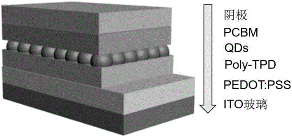
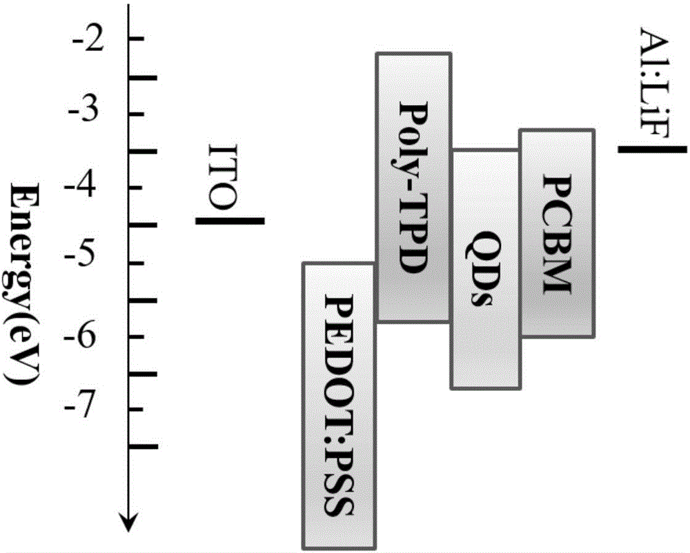
[0025] The ITO glass was placed in acetone, ethanol, and ultrapure water in sequence, and ultrasonically cleaned for 20 minutes, and dried for use after cleaning. Put the cleaned ITO glass in a UV-ozone analyzer for 10 minutes. Add isopropanol (PEDOT:PSS: isopropanol = 20:1) to PEDOT:PSS to adjust the viscosity, filter the prepared PEDOT:PSS isopropanol solution with a 0.45μm aqueous needle filter to remove Small amounts of slightly larger particulate matter in the solution. Next, QLEDs are prepared sequentially from anode to cathode (the energy level structure diagram is as figure 2 ), the preparation sequence is: spin-coating the filtered PEDOT:PSS solution on the ITO anode. The spin-coating process of PEDOT:PSS is: high-speed 4000rpm, time 30s, and then placed on a hot stage at 120°C for 15min annealing to form a void Hole injection layer film; deposit a poly-TPD chlorobenzene solution with a mass fraction of 1.5% on the PEDOT:PSS film. The spin coating process of Poly-TPD...

Embodiment 2

[0027] The ITO glass was placed in acetone, ethanol, and ultrapure water in sequence, and ultrasonically cleaned for 20 minutes, and dried for use after cleaning. Put the cleaned ITO glass in a UV-ozone analyzer for 10 minutes. Add isopropanol (PEDOT:PSS: isopropanol = 20:1) to PEDOT:PSS to adjust the viscosity, filter the prepared PEDOT:PSS isopropanol solution with a 0.45μm aqueous needle filter to remove Small amounts of slightly larger particulate matter in the solution. Next, QLEDs are prepared sequentially from anode to cathode (the energy level structure diagram is as Figure 4 ), the preparation sequence is: spin-coating the filtered PEDOT:PSS solution on the ITO anode, the spin-coating process of the PEDOT:PSS solution is: high-speed 4000rpm, time 30s, and then placed on a hot stage at 120°C and annealed for 15min to form Hole injection layer film; the configured toluene solution of PVK with a mass fraction of 2% is deposited on the PEDOT:PSS film, and then annealed ...

Embodiment 3

[0029] The ITO glass was placed in acetone, ethanol, and ultrapure water in sequence, and ultrasonically cleaned for 20 minutes, and dried for use after cleaning. Put the cleaned ITO glass in a UV-ozone analyzer for 10 minutes. Add isopropanol (PEDOT:PSS: isopropanol = 20:1) to PEDOT:PSS to adjust the viscosity, filter the prepared PEDOT:PSS isopropanol solution with a 0.45μm aqueous needle filter to remove Small amounts of slightly larger particulate matter in the solution. Next, QLEDs are prepared sequentially from anode to cathode (the energy level structure diagram is as figure 2 ), the preparation sequence is: spin-coating the filtered PEDOT:PSS solution on the ITO anode, the spin-coating process of the PEDOT:PSS solution is: high-speed 3000rpm, time 30s, and then put it on a hot stage at 120℃ for 15min annealing to form Hole injection layer thin film; the prepared poly-TPD chlorobenzene solution with a mass fraction of 2.5% is deposited on the PEDOT:PSS film. The spin c...


PUM


Abstract

The invention relates to a quantum-dot light-emitting diode and a preparation method therefor. The structure of the light-emitting diode sequentially comprises an anode, a hole injection layer, a hole transmission layer, a quantum-dot light-emitting layer, an electron transmission layer, and a cathode. The electron transmission layer is a [6, 6]-phenyl-C61-methyl butyrate PCBM film. The preparation method is a spin coating method. According to the invention, the electron transmission layer can effectively improve the exciton recombination probability and the luminous efficiency of a device. Meanwhile, the quantum-dot light-emitting diode is a typical sandwich structure, and the spin coating method is employed for layer-by-layer assembly. The preparation method is simple and feasible, facilitates the preparation of a large-area light-emitting device, and is widely used in the field of quantum-dot light-emitting diodes.

Description

Technical field [0001] The invention belongs to the field of light emitting devices, and particularly relates to a quantum dot light emitting diode and a preparation method thereof. Background technique [0002] Quantum dot light-emitting diodes (QLEDs) have the advantages of high brightness, stable solution process, adjustable band gap, good stability, high color saturation, low energy consumption, low heat generation, and long service life. They are used in lighting and flat panel displays. The field has received extensive attention from people. The first generation of organic light-emitting diodes is a small molecule organic device that uses an organic double-layer structure composed of a sandwich structure. However, a high-efficiency QLED requires a multi-layer structure to balance the transfer of carriers and facilitate the recombination of excitons to emit light. In the late 1990s, the structure of organic light-emitting diodes was more complicated, and a multi-layered de...

Claims


Application Information

Patent Timeline
IPC IPC(8): H01L33/06H01L33/00H01L51/50H01L51/56
CPCH01L33/005H01L33/06H10K50/15H10K71/00
Inventor 李耀刚王艳伟李佳慧王宏志张青红
Owner DONGHUA UNIV
Why Eureka
Try Eureka