
Liquid-state die forging process for cam shaft gear for automobile engine

A technology for camshaft gears and automobile engines, which is applied in the manufacture of tools, metal processing equipment, coatings, etc. It can solve problems such as the production process of camshaft gears that have not been mentioned, and achieve reasonable design of process steps, improve efficiency, and improve material utilization rate effect

Inactive Publication Date: 2017-02-15
JIANGSU BAOJIE FORGING
View PDF4 Cites 5 Cited by
  • Summary
  • Abstract
  • Description
  • Claims
  • Application Information

AI Technical Summary

Problems solved by technology

However, this patent mainly provides precision forging dies for camshaft gears, and does not mention the specific production process of camshaft gears

Method used


Image

  • Liquid-state die forging process for cam shaft gear for automobile engine
  • Liquid-state die forging process for cam shaft gear for automobile engine
  • Liquid-state die forging process for cam shaft gear for automobile engine

Examples


Embodiment Construction

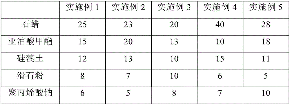
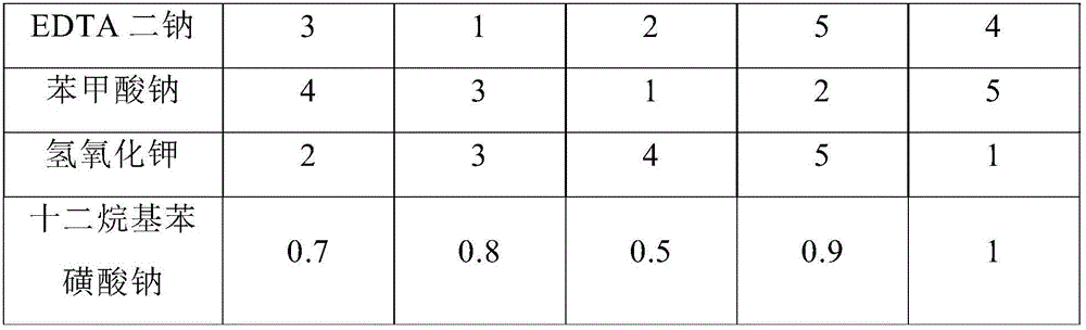
[0044] The following examples are used to illustrate the present invention, but should not be used to limit the scope of the present invention. The implementation conditions used in the examples can be further adjusted according to the manufacturer's conditions, and the unspecified implementation conditions are usually conventional experimental conditions.

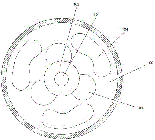
[0045] see figure 1 , the camshaft gear obtained by the liquid die forging process of a camshaft gear for an automobile engine provided by the present invention includes a disc 100, a through hole 101 is opened in the middle, and a ring 102 is set on the surface of the through hole 101, and the outer circumference of the ring 102 is Three arc-shaped bosses 103 are equidistantly spaced, and three openings 104 are equidistantly spaced along the circumference of the through hole 101 on the surface of the disc 100 .

[0046] The invention provides a liquid die forging process for a camshaft gear used in an automobile engine. ...


PUM


Abstract

The invention provides a liquid-state die forging process for a cam shaft gear for an automobile engine. The liquid-state fie forging process comprises the following steps of: 1) smelting; 2) mould designing; 3) liquid-state die forging; 4) normalizing; 5) turning; 6) carburizing and quenching; 7) tempering; 8) grinding; 9) shot blasting and flaw detecting; 10) phosphorus saponification treatment, clearing, polishing and anti-rust oil coating. The process adopts a liquid-state die forging process to carry out gear processing forging, saves labor and energy, and is high in material utilization rate; blank is close to a final processing gear of a cam shaft gear, and die forging quality is high; the obtained gear is high in hardness, is good in wear resistance, is high in corrosion resistance and is low in forging cost; and the forging process is environmentally-friendly.

Description

technical field [0001] The invention relates to a liquid die forging process for a camshaft gear used in an automobile engine. Background technique [0002] The car engine is the engine that provides power for the car. It is the heart of the car and affects the power, economy and environmental protection of the car. According to different power sources, automotive engines can be divided into diesel engines, gasoline engines, electric vehicle motors, and hybrids. [0003] The camshaft is a component in a piston engine. Its function is to control the opening and closing of the valve. Although the speed of the camshaft in a four-stroke engine is half that of the crankshaft (the speed of the camshaft is the same as that of the crankshaft in a two-stroke engine), it usually still has a high speed and needs to withstand a large torque, so the design of The camshaft has high requirements on strength and support, and its material is generally special cast iron, and occasionally f...

Claims


Application Information

Patent Timeline
IPC IPC(8): C22C38/02C22C38/04C22C38/18C22C38/06C22C38/08C22C38/12C22C38/32B22D18/02C21D1/28C21D1/18C21D9/32B23P15/14B22C3/00C23C8/22
CPCC22C38/02B22C3/00B22D18/02B23P15/14C21D1/18C21D1/28C21D9/32C22C38/04C22C38/06C22C38/08C22C38/12C22C38/18C22C38/32C23C8/22
Inventor 甘元张添鑫陆以春陈波易立王正国
Owner JIANGSU BAOJIE FORGING
Learn More