Oily sludge treatment system and treatment method thereof

A treatment system and sludge technology, applied in sludge treatment, water/sludge/sewage treatment, dehydration/drying/thickened sludge treatment, etc., can solve the problem of expensive chemicals, difficult to remove debris, hindering equipment and Facility operation and other issues, to achieve outstanding results

Pending Publication Date: 2017-05-31
仇霞霞
View PDF16 Cites 30 Cited by
  • Summary
  • Abstract
  • Description
  • Claims
  • Application Information

AI Technical Summary

Problems solved by technology

However, its core technology is a high-speed centrifugal three-phase separation device, which is basically monopolized by countries such as Europe and the United States. It is still difficult for China to produce such devices
Disadvantages of tempering-separation technology: due to the variety of oily sludge, the combination of existing dehydration machinery and agents is not universally applicable
However, this method is only suitable for crude oil recovery and treatment of ground crude oil and oil sands with high oil content and light emulsification, and it is not suitable for the treatment of oil sludge with severe emulsification; it needs to add a large amount of expensive chemical agents, resulting in high cost; processing The oil content in the residue after separation is high, and the water content of the sludge residue after separation is greater than 90% and contains a large amount of chemic

Method used


Image

  • Oily sludge treatment system and treatment method thereof
  • Oily sludge treatment system and treatment method thereof
  • Oily sludge treatment system and treatment method thereof

Examples


Embodiment 1

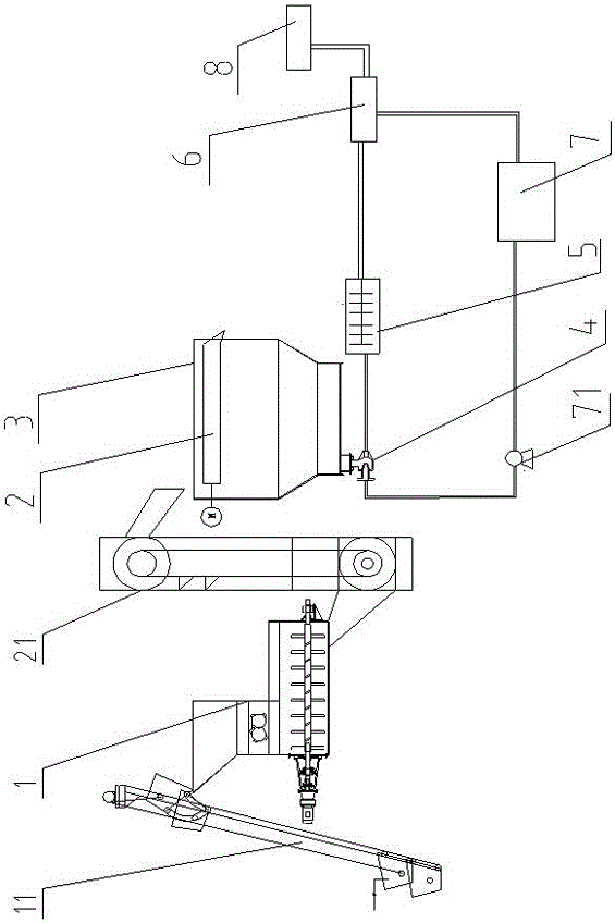
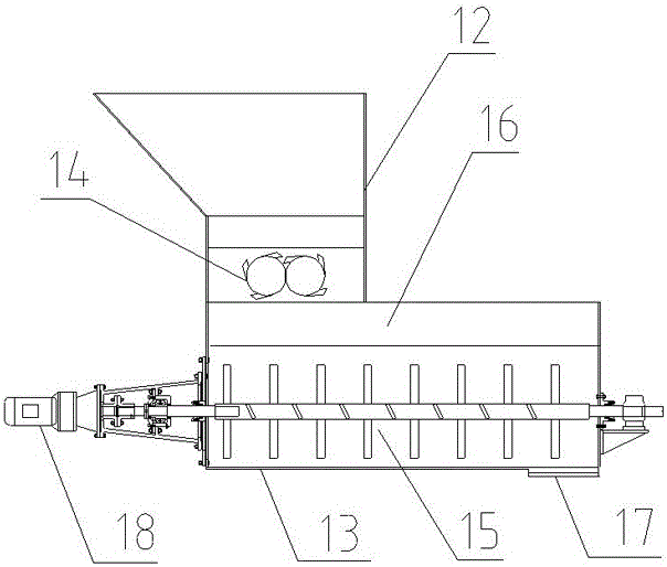
[0103] refer to Figure 1-5 , the present invention will be further illustrated by the following examples.

[0104] The specific embodiment of the present invention is illustrated by taking the oil tank bottom sludge (the sludge contains 30wt% oil, 35wt% water, and the rest is solid matter).

[0105] (1) Transport the oily sludge to the crushing equipment 1 for crushing, and at the same time spray hot water (temperature 80°C) with a high-pressure water spray device to spray and grind the oily sludge. After the crushing equipment 1 completes the crushing and spraying Stand still after washing, then open the first oil slick discharge port and discharge the upper layer of slick oil and sundries (sawdust, grass, plastic, etc.), and the lower layer of oily sludge is discharged and transported to the vibrating screen 2; The weight ratio of the output water to the oily sludge is preferably 1:1.

[0106] (2) The vibrating screen 2 screens the oily sludge, and the debris (bricks, sto...

Embodiment 2

[0111] As another embodiment of the present invention, it is basically the same as the treatment method of Example 1, except that in step (4), the extraction agent is passed into the feed port 617 at the bottom of the separation device, and the extraction agent is toluene, The dosage of the extractant is 0.5wt% of the oily sludge. The final oil recovery rate was 98.3%, and the residual oil rate was 1.5%.


PUM

PropertyMeasurementUnit
Granularityaaaaaaaaaa

Abstract

The invention discloses an oily sludge treatment system and a treatment method thereof. The treatment system comprises crushing equipment, a vibrating screen, a precipitation device, an ejector, a high-speed crushing device, a water storage device and separation device for separating oil, water and sludge, wherein the crushing equipment is used for primarily crushing oily sludge and is provided with an oil slick space and a first oil slick outlet which can be opened and closed; the vibration screen is located at the upper part of the precipitation device; the precipitation device is used for precipitating the screened oily sludge; the high-speed crushing device is used for crushing the oily sludge into fine particles; the precipitation device is sequentially connected with the ejector, the high-speed crushing device and the separation equipment; a water outlet of the water storage device is connected with a water inlet of the ejector. The treatment system can be applicable to dewatering of various oily sludges, meanwhile, the oil rate of the oily sludge can be reduced to below 3%, oil can be recovered to the maximal extent and secondary pollution of wastewater is not generated.

Description

technical field [0001] The invention relates to a treatment system and a treatment method for oily sludge. Background technique [0002] Oil sludge mainly refers to the oily sludge formed by crude oil or other oil products and soil due to various reasons, as well as the oily sediment brought out by the system in the normal production of oilfields. It is a solid waste rich in mineral oil. The ingredients are crude oil, mud and water. The solid particle size can range from sub-micron to several inches. The composition of the oil depends on the type of crude oil, refinery structure and operating conditions. The composition of the sludge may change over time. Usually the sludge contains a certain amount of crude oil, heavy metal ions (such as iron, copper, nickel, etc.) and inorganic salt compounds. These oil sludges generally contain benzene series, phenols and other substances, and are accompanied by odor and toxicity. If they are directly in contact with the natural environ...

Claims


Application Information

Patent Timeline
IPC IPC(8): C02F11/00C02F11/12C10G1/04C10G1/00B02C18/14B02C4/08B02C23/02B07B1/28
CPCC10G1/00C10G1/045C02F11/00C02F11/127B02C4/08B02C18/141B02C23/02B07B1/28C02F2101/32C02F2103/365C02F2103/10C02F2303/06C10G2300/1003
Inventor 仇霞霞李艺凡冷增冰
Owner 仇霞霞
Why Eureka
Try Eureka