Low-inertia quick-response metal-ceramic composite turbine rotary shaft

A fast-response, metal-ceramic technology, applied in the direction of turbines, metal processing equipment, blade support components, etc., can solve problems such as performance attenuation, high melting point, structural evolution damage, etc., to achieve improved transient response, mature and reliable technology, The effect of solving connection difficulties

Active Publication Date: 2017-08-11
北京领动国创科技有限公司
View PDF5 Cites 2 Cited by
  • Summary
  • Abstract
  • Description
  • Claims
  • Application Information

AI Technical Summary

Problems solved by technology

However, the application of ceramic turbines is mainly restricted by two aspects: one is that due to its high brittleness and low ductility, it faces the problem of thermal shock damage under extremely harsh service conditions, and the formed thermal shock damage is in the structure under long-term high temperature and responsible load Evolutionary damage and sharp performance attenuation, the reliability of silicon nitride turbine rotors is severely challenged
On the other hand, due to its high melting point, the connection between the silicon nitride ceramic turbine and the high temperature steel 42CrMo shaft has become a major problem restricting its application.

Method used


Image

  • Low-inertia quick-response metal-ceramic composite turbine rotary shaft
  • Low-inertia quick-response metal-ceramic composite turbine rotary shaft

Examples


Embodiment Construction

[0018] The present invention will be further described in detail below in conjunction with the accompanying drawings.

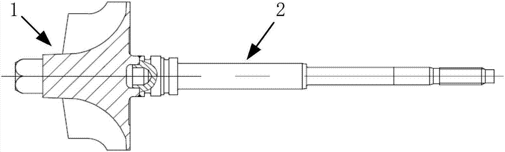
[0019] The low-inertia, fast-response metal-ceramic composite turbine shaft includes a composite material turbine 1 and a high-temperature-resistant steel shaft 2 welded together, such as figure 1 shown.

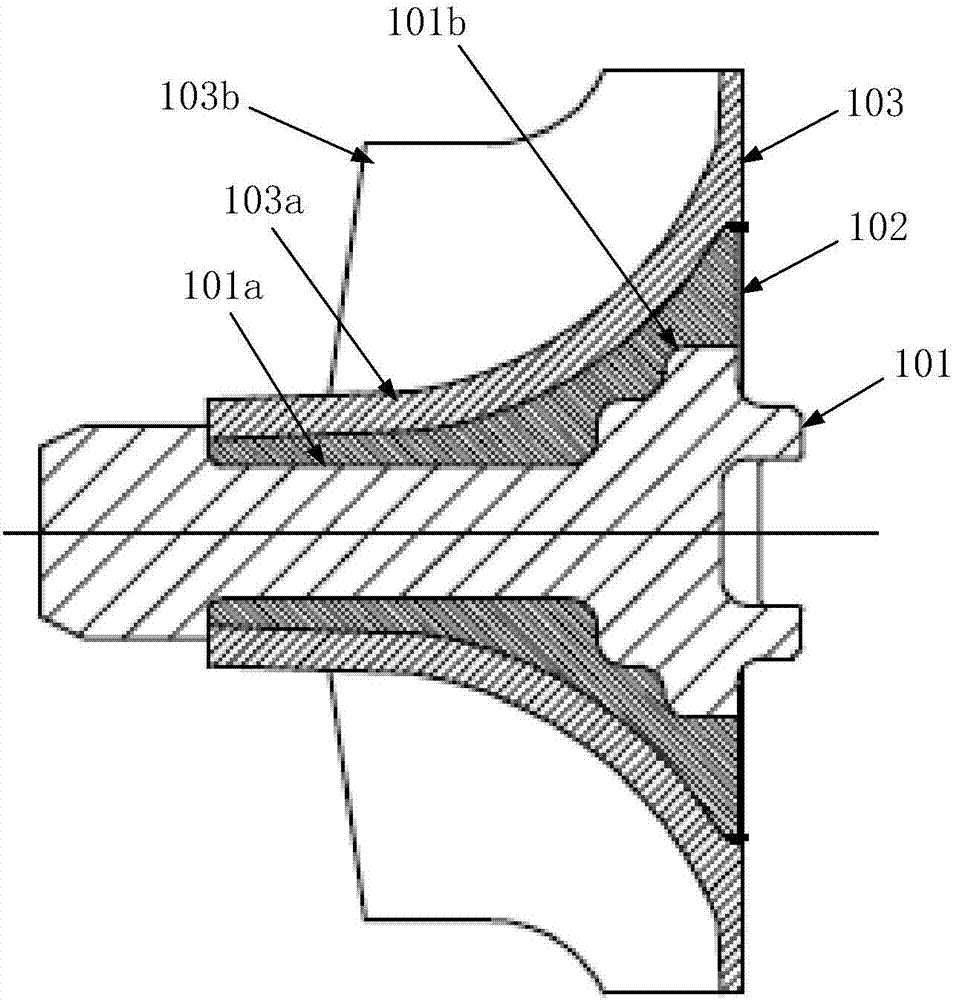
[0020] The composite material turbine 1 is divided into a three-layer structure from the inside to the outside, which are respectively the inner body 101, the transition layer 102 and the blade layer 103, as figure 2 shown. Wherein, the inner body 101 is made of traditional nickel-based alloy steel, which is a uniform rotator manufactured by casting. Specifically: the nickel-based alloy steel is nickel-based alloy steel K418, with a density of 8.0kg / cm^3, a linear expansion coefficient of 12.6e-6 / °C, a thermal conductivity of 10.15W / m.°C, and a heat resistance of 800°C.

[0021] The transition layer 102 is a superalloy powder sintered to the inner body....


PUM

PropertyMeasurementUnit
thermal resistanceaaaaaaaaaa
thicknessaaaaaaaaaa

Abstract

The invention discloses a low-inertia quick-response metal-ceramic composite turbine rotary shaft. The low-inertia quick-response metal-ceramic composite turbine rotary shaft comprises a turbine and a rotary shaft body. The turbine is divided into three structure layers from inside to outside and comprises an inner main body, a transition layer and blade layer. The inner main body is made from traditional nickel-based alloy steel is a uniform rotation body manufactured through a casting molding method. The transition layer adopts high-temperature alloy powder and is sintered onto the inner main body. The blade layer adopts a mixed ceramic material of silicon nitride and zirconium oxide and is provided with a hub surface layer and turbine blades peripherally arranged on the outer wall of an axle. The rotary shaft body is made from high-temperature-resistant steel, and one end of the rotary shaft body is coaxially connected with a composite wheel in a hollow friction welding mode. The turbine rotary shaft is formed by compositing the multiple materials of nickel-based alloy steel-high-temperature alloy powder-ceramic, the mass of the turbine is lowered, and thus the effect that the turbine can bear the 1050 DEG C high temperature working environment is achieved; and compared with high-temperature-resistant steel rotary shafts of the same material and traditional friction welding processes, connection is reliable, the manufacturing cost is low, and the purpose of improving the responsiveness of an engine is achieved.

Description

technical field [0001] The invention relates to the technical field of turbocharging, in particular to a low-inertia, fast-response metal-ceramic composite turbine rotating shaft of a turbocharger. Background technique [0002] The turbocharger is installed on the exhaust pipe of the engine, and the turbine casing is directly connected to the exhaust pipe. It is under high temperature and high pressure working conditions, especially in aviation piston engines and passenger car gasoline engines, where the exhaust temperature is as high as 950 °C ~1050°C, which is much higher than the maximum exhaust temperature of a diesel engine at 850°C, and the traditional nickel-based alloy turbine can no longer meet its performance requirements. Moreover, the density of the nickel-based alloy is high, and the mass of the turbine is heavy, which causes the response delay of the turbocharger to be obvious. Therefore, around the two major problems of high temperature resistance and low qua...

Claims


Application Information

Patent Timeline
Patent Type & Authority Applications(China)
IPC IPC(8): F01D5/02B22C9/04B22F7/08B22F5/04B22F3/22
CPCB22C9/04B22F3/225B22F5/04B22F7/08F01D5/02
Inventor 周煜姬芬竹李亚静刘勐
Owner 北京领动国创科技有限公司
Why Eureka
Try Eureka