Insulated oil pipe and preparation method thereof

A technology for oil pipes and insulation layers, applied in the field of pipelines, can solve problems such as waste of resources and collection and transportation costs, increased oil flow resistance, increased oil friction resistance, etc., to achieve reduced friction, long service life, and light weight Effect

Pending Publication Date: 2017-09-05
大连辉华新材料有限公司
View PDF10 Cites 10 Cited by
  • Summary
  • Abstract
  • Description
  • Claims
  • Application Information

AI Technical Summary

Problems solved by technology

[0002] At present, regardless of the oil recovery methods used in major oilfields in China, the temperature of the oil drops greatly while the viscosity increases during the process of the oil from the oil layer to the ground. In addition to the oil outlet temperature, when the crude oil rises from the underground oil layer to the surface, the temperature of the crude oil is basically slightly higher than the formation temperature at the same position, from 55-130°C in the oil layer to 15-30°C. Smaller, during production in winter, the temperature of the oil when it reaches the surface wellhead is only 15°C to 20°C, which is far below the freezing point (the freezing point of crude oil is generally 30°C to 38°C), and the viscosity of crude oil in the underground oil layer (thin oil) Generally, it is 4-5mpa.s (close to the viscosity of edible salad oil). From this point of view, the viscosity of crude oil increases several times during the lifting process in the oil pipe. In many cases, the viscosity of the oil to the ground is the viscosity when it is in the oil layer. 9 times more than that of the oil, and the decrease of the oil temperature leads to the increase of the viscosity, which increases the frictional resistance of the oil in the pipeline. Therefore, a greater power consumption of the pumping machine is required to maintain the production. Moreover, the increase of the viscosity directly leads to the increase of the oil The flow resistance of oil increases, and when the oil reaches the ground, the fluidity has deteriorated, and hot water is often required for transportation, resulting in waste of resources and collection and transportation costs

Method used


Image

  • Insulated oil pipe and preparation method thereof

Examples


preparation example Construction

[0024] In this embodiment, the preparation method of the thermal insulation oil pipe includes the following steps:

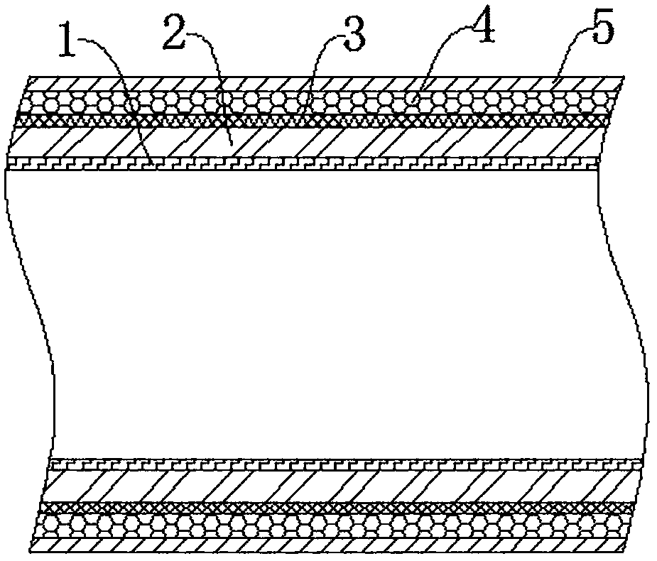
[0025] Step 1: Treat the surface of the oil pipe base 2, clean the outer surface and inner surface of the oil pipe base 2 until it is free of dust, oil, water and other attachments, and then set aside;

[0026] Step 2: Apply clay evenly on the inner surface of the tubing base 2, and then sinter;

[0027] Step 3: Prepare the material of the thermal insulation layer 3, and spray the airgel thermal insulation coating or the nano-modified polyurethane composite thermal insulation coating by molding or the other nano thermal insulation coatings by bonding The process is applied on the outer surface of the tubing matrix 2;

[0028] Step 4: After the thermal insulation layer 3 in the above step 3 is dried, wrap or socket the material of the protective layer 4 on the outer surface of the thermal insulation layer 3;

[0029] Step 5: Wrap the material of the anti-corros...

Embodiment 1

[0031] In this embodiment, in the step 3, the airgel thermal insulation coating is sprayed on the outer surface of the tubing base 2 as the thickness of the thermal insulation layer 3 is 3 mm, and the airgel thermal insulation coating The material used for the layer is mixed and stirred from the following ingredients, including: nano airgel 10%, lithium titanate whisker 8%, inorganic fiber powder 15%, polysulfone resin 10%, 901 airgel special adhesive 10% agent, 5% glass powder, 2% silane coupling agent, 5% nano-boron carbide, and the rest is deionized water.

[0032] In this embodiment, in the step 4, when the protective layer 4 is made of glass fiber reinforced plastic composite glass fiber protective layer 4, the winding thickness is 1.5 mm.

[0033] In this embodiment, in the step 5, the anti-corrosion layer 5 is sprayed on the outside of the protective layer 4 with a strong anti-corrosion rubber resin, with a thickness of 0.2mm.

[0034] The properties of the obtained th...

Embodiment 2

[0040] In this embodiment, in the step 3, the material used in the nano-modified polyurethane composite thermal insulation coating is mixed and stirred from the following components, including: polyurethane rigid foam combined polyether 30%, polymerized MDI, 30%, nano airgel 30%, carbon nanotube 5%, polysilazane 2%, polynonylidene urea 3%, the thickness of the nano-modified polyurethane composite thermal insulation coating is 5mm.

[0041] In the present embodiment, in the step 4, the protective layer 4 is sleeved on the surface of the thermal insulation layer 3 with a rubber heat-shrinkable tube sleeve, and shrunk by hot air at 150° C., with a thickness of 1 mm.

[0042] In this embodiment, in the step 5, the anti-corrosion layer 5 is sprayed with polyurea paint, with a thickness of 1mm;

[0043] The properties of the obtained thermal insulation oil pipe are as follows:

[0044] The apparent thermal conductivity is: 0.021w / m.k;

[0045] Maximum temperature resistance: 170°C...


PUM


Abstract

The invention discloses an insulated oil pipe. The insulated oil pipe comprises an oil pipe base body. A ceramic glaze is arranged on the inner surface of the oil pipe base body. An insulating layer is arranged on the outer surface of the oil pipe base body. A protective layer is arranged on the outer surface of the insulating layer. An anticorrosion layer is arranged on the surface of the protective layer. The insulated oil pipe has the beneficial effects that the inner wall is smooth, the friction force generated when oil flows can be greatly reduced, the weight is low, the insulating effect and the anticorrosion effect are both good, the service life is long, no energy needs to be additionally consumed during use, and the cost performance is high.

Description

technical field [0001] The invention relates to the field of pipelines, in particular to a thermal insulation oil pipe and a preparation method thereof. Background technique [0002] At present, regardless of the oil recovery methods used in major oilfields in China, the temperature of the oil drops greatly while the viscosity increases during the process of the oil from the oil layer to the ground. In addition to the oil outlet temperature, when the crude oil rises from the underground oil layer to the surface, the temperature of the crude oil is basically slightly higher than the formation temperature at the same position, from 55-130°C in the oil layer to 15-30°C. Smaller, during production in winter, the temperature of the oil when it reaches the surface wellhead is only 15°C to 20°C, which is far below the freezing point (the freezing point of crude oil is generally 30°C to 38°C), and the viscosity of crude oil in the underground oil layer (thin oil) Generally, it is 4...

Claims


Application Information

Patent Timeline
Patent Type & Authority Applications(China)
IPC IPC(8): F16L59/02F16L59/10F16L58/14F16L58/18
CPCF16L58/14F16L58/18F16L59/028F16L59/029F16L59/10
Inventor 倪箐华
Owner 大连辉华新材料有限公司
Why Eureka
Try Eureka