Catalytic combustion heating system and heating technology

A catalytic combustion and heating system technology, applied in the direction of combustion method, combustion type, lighting and heating equipment, etc., can solve the problems of increased floor area and large floor area of ​​heat transfer oil system, so as to improve the utilization rate of heat energy, Ease of heat recovery and low reaction temperature

Inactive Publication Date: 2017-11-07
ALLY HI TECH CO LTD
View PDF9 Cites 6 Cited by
  • Summary
  • Abstract
  • Description
  • Claims
  • Application Information

AI Technical Summary

Problems solved by technology

Due to the particularity of the open flame device, according to the relevant national regulations, the safe distance between the open flame device and the hydrogen device must not be less than 15m, and the heat transfer oil system itself occupies a large area, which makes the entire chemical device occupy a large area due to the heat carrier heating unit. increase

Method used


Image

  • Catalytic combustion heating system and heating technology
  • Catalytic combustion heating system and heating technology
  • Catalytic combustion heating system and heating technology

Examples


Embodiment 1

[0035] 100Nm 3 / h Methanol Steam Reforming Hydrogen Production Heat Transfer Oil Heating System

[0036] 100Nm 3 / h Methanol steam hydrogen production in the raw material methanol and desalted water vaporization superheating and conversion reaction requires heat, the total heat required is 103kw, the heating carrier is No. 320 heat transfer oil, the temperature of the heat transfer oil entering and leaving the methanol hydrogen production device is 270 °C and 260 °C respectively ℃. In the process of hydrogen purification, tail gas emission is 57Nm3 / h tail gas (hydrogen yield 85%), and the gas composition is H 2 : 30.6%, CO: 1.7%, CO 2 : 67.1%, CH 4 : 0.4% and saturated water. With increasingly stringent environmental protection requirements, the tail gas must be treated before being discharged.

[0037] The methanol water steam reforming heat conduction oil heat supply system adopting the technology of the present invention uses methanol as the supplementary fuel and Pt / ...

Embodiment 2

[0041] 1200Nm 3 / h Methanol Steam Reforming Hydrogen Production Heat Transfer Oil Heating System

[0042] 1200Nm 3 / h methanol and desalted water vaporization superheating and conversion reaction of raw material methanol and water vapor hydrogen production require heat, the total heat required is 1212kw, the heating carrier is No. 320 heat transfer oil, and the temperature of the heat transfer oil entering and exiting the methanol hydrogen production device is 270°C and 260°C . Tail gas emission during hydrogen purification process is 647Nm 3 / h tail gas (hydrogen yield 87%), the gas composition is H 2 : 27.7%, CO: 1.8%, CO 2 : 69.8%, CH 4 : 0.4% and saturated water.

[0043] The methanol water vapor reforming heat conduction oil heat supply system adopting the technology of the present invention uses methanol as the supplementary fuel and Pd / Al as the catalyst 2 o 3 The catalyst and catalyst carrier adopt ceramic honeycomb blocks, which can reduce the resistance drop ...

Embodiment 3

[0047] 10t / h medium pressure steam heating system

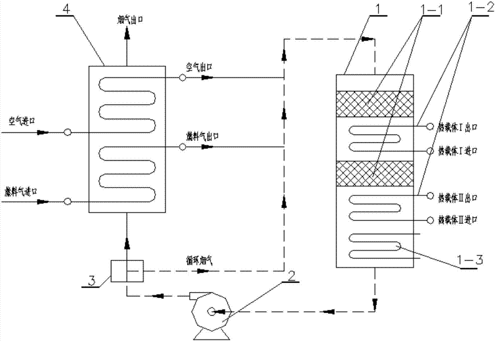
[0048] Exhaust gas from a chemical plant is about 3500Nm 3 / h, the gas composition is H 2 : 31%, CO: 3.5%, CH 4 : 12.5%, CO 2 :30% :N 2 : 21%, C 2+ : 2%, generally enters the flare system and empties after combustion. And the public works medium pressure steam of factory area is short of all the time, the medium pressure steam that adopts the system of the present invention intends to produce 10t / h is used as the public works supplementary steam of factory area. The catalyst is Pd / Al 2 o 3 The catalyst and catalyst carrier adopt honeycomb block shape, which can reduce the resistance drop of the system and save the power consumption of the circulation device. Due to the exhaust gas has a certain back pressure, the system adopts figure 1 In the process shown, the heat exchange coil adopts two layers, the high temperature side is the steam generation coil, and the bottom is the boiler feed water preheating coil. Since ...


PUM


Abstract

The invention discloses a catalytic combustion heating system and belongs to the technical field of catalytic combustion heating and environmental protection. With the system, a heat carrier is heated by heat released by a catalytic combustion reaction. The system comprises a catalytic combustion reaction heating zone, a flow control unit and a flue gas circulating device which is connected with the catalytic combustion reaction heating zone and the flow control unit in a communicating manner; and the catalytic combustion reaction heating zone is connected with the flow control unit in a communicating manner. The invention further relates to a technology for heating with the system. With the system and the technology, industrial waste gas is used as a heat source to provide heat for feed gas and the heat carrier which are required to be preheated, so that the heat utilization rate can be increased, the energy consumption can be reduced, the industrial waste gas is reused, the production cost is reduced, and environmental pollution is reduced. The catalytic combustion temperature is low, the complete reaction is realized, the energy consumption is low, the operation is simple and safe, and the purification efficiency is high. With the system, the land occupied by equipment can be effectively reduced, the cost can be reduced, and resource waste can be reduced.

Description

technical field [0001] The invention belongs to the technical field of catalytic combustion heating and environmental protection, and in particular relates to a catalytic combustion heating system and a heating process. Background technique [0002] At present, the amount of industrial waste gas discharged by industrial enterprises is increasing year by year. Most of these industrial waste gases contain combustible components such as hydrogen, methane, ethane, ethylene, light hydrocarbons above C3, and CO, which have great recovery and utilization value, but the recovery of these The components are technically difficult, the adsorbent needs to be replaced regularly, and the operating cost is high. In addition, the combustible components in the tail gas have not been effectively utilized, resulting in waste of resources. At the same time, chemical companies often need heat carriers such as steam or heat transfer oil at a certain temperature and pressure for specific chemical...

Claims


Application Information

Patent Timeline
Patent Type & Authority Applications(China)
IPC IPC(8): F23G7/07F23G5/46
CPCF23G5/46F23G7/07F23G2202/60F23G2206/20F23G2209/14Y02A50/20
Inventor 王业勤叶根银
Owner ALLY HI TECH CO LTD
Why Eureka
Try Eureka