A CO cryogenic separation system and method using nitrogen cycle
A cryogenic separation and nitrogen cycle technology, applied in hydrogen separation, carbon monoxide and other directions, can solve the problems of low efficiency of CO compressor and expander, large amount of venting in the start-up stage, and low pressure of CO product gas, so as to reduce the amount of venting, The effect of reducing distillation power consumption and low investment
- Summary
- Abstract
- Description
- Claims
- Application Information
AI Technical Summary
Problems solved by technology
Method used
Image
Examples
Embodiment 1
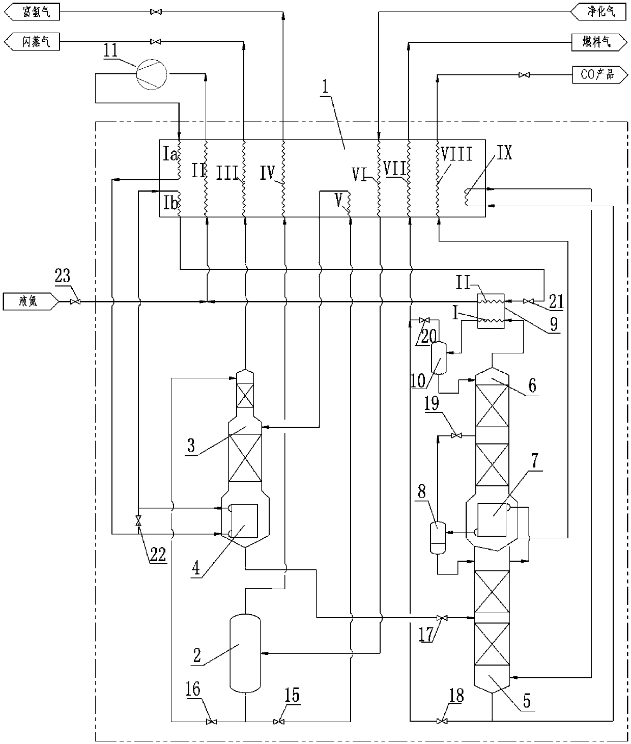
[0030] Embodiment one: if figure 1As shown, a CO cryogenic separation system adopting nitrogen circulation includes a main heat exchanger 1, a low-temperature separator 2, a hydrogen stripper 3, a hydrogen stripper bottom evaporator 4, a demethanizer 5, and a demethanizer 5. Nitrogen tower 6, condensing evaporator 7, demethanizer overhead separator 8, denitrification tower overhead condenser 9, denitrification tower overhead separator 10, and circulating nitrogen compressor 11; inside the main heat exchanger 1 Provided with flow channel Ia, flow channel Ib, flow channel II, flow channel III, flow channel IV, flow channel V, flow channel VI, flow channel VII, flow channel VIII and flow channel IX; denitrification tower top condenser 9 Flow channel I and flow channel II are arranged inside, the hydrogen stripper tower bottom evaporator 4 is arranged in the hydrogen stripper tower 3 and is located at its bottom, and the condensation evaporator 7 is connected between the demethani...
Embodiment 2
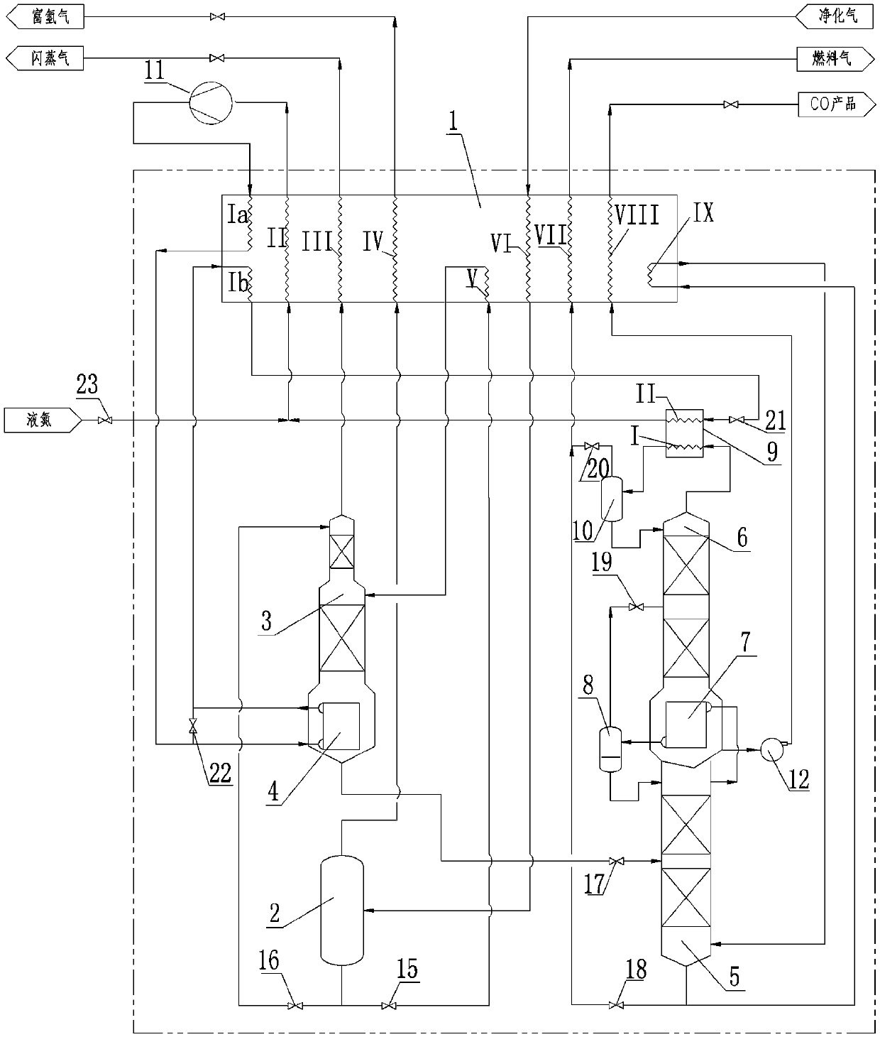
[0044] Embodiment two: if figure 2 As shown, the difference between this embodiment and Embodiment 1 is that a CO liquid pump 12 is added between the liquid-phase outlet of the denitrification tower 6 and the inlet of the flow channel VIII of the main heat exchanger 1, and the discharge of the circulating nitrogen compressor 11 can be The gas pressure is reduced to 2.1MPa.G, the operating pressure of demethanizer 5 is reduced to 0.6MPa.G, and the operating pressure of denitrification tower 6 is reduced to 0.3MPa.G, thereby further reducing system power consumption.
Embodiment 3
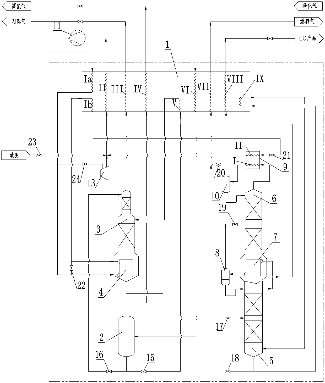
[0045] Embodiment three: as image 3 As shown, the difference between the present embodiment and the first embodiment is that a flow of material is added at the outlet of the main heat exchanger 1 internal flow passage Ia, and is sent to the inlet of the turbo expander 13 after passing through the valve k24, and the turbo expander 13 The outlet of the outlet is connected with the low-pressure nitrogen main pipe, and when the system is started or the cooling capacity is insufficient, the turbo expander 13 is used to produce cooling capacity.
PUM
 Abstract
Description
Claims
Application Information
 - R&D
- Intellectual Property
- Life Sciences
- Materials
- Tech Scout
- Unparalleled Data Quality
- Higher Quality Content
- 60% Fewer Hallucinations
Browse by: Latest US Patents, China's latest patents, Technical Efficacy Thesaurus, Application Domain, Technology Topic, Popular Technical Reports.
© 2025 PatSnap. All rights reserved.Legal|Privacy policy|Modern Slavery Act Transparency Statement|Sitemap|About US| Contact US: help@patsnap.com


