Preparation method of n-shaped double-surface solar cell

A double-sided solar cell, n-type technology, applied in circuits, photovoltaic power generation, electrical components, etc., can solve the problem that emitter passivation and anti-reflection cannot be optimized at the same time, battery electrode contact resistance and series resistance are high, and cannot be passivated. In order to improve the overall electrical conversion efficiency, reduce the sintering temperature, achieve the best passivation performance and contact performance.

Inactive Publication Date: 2018-05-15
TAIZHOU LERRISOLAR TECH CO LTD
View PDF5 Cites 8 Cited by
  • Summary
  • Abstract
  • Description
  • Claims
  • Application Information

AI Technical Summary

Problems solved by technology

[0004] The purpose of the present invention is to provide a preparation method of n-type double-sided solar cells to solve the traditional sintering in the prior art, the temperature is high, and the passivation performance of the emitter and the back field of the cell has a relatively large negative impact , the contact resistance and series resistance of battery electrodes are relatively high, and the battery sintering process window is narrow, because it involves multiple electrode components and multiple passivation structures, which cannot achieve the best passivation performance and contact performance at the same time, and currently The emitter of the solar cell is on the front side, so that the passivation and anti-reflection of the emitter cannot be optimized at the same time. The above shortcomings make the current n-type solar cells unable to achieve the best cell conversion efficiency.

Method used


Image

  • Preparation method of n-shaped double-surface solar cell
  • Preparation method of n-shaped double-surface solar cell
  • Preparation method of n-shaped double-surface solar cell

Examples


Embodiment 1

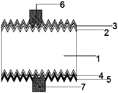
[0036] As an example, such as figure 1 , the preparation method of this n-type double-sided solar cell is as follows:

[0037] 1) Dedamaging and cleaning the n-type silicon substrate 1 . Use NaOH solution for damage treatment, and use hydrofluoric acid, hydrochloric acid for cleaning.

[0038] 2) The emitter is prepared on the back side of the silicon substrate 1 . A BBr3 tubular diffusion process is performed to prepare a pn junction and a p+ doped layer 4 on the back of the silicon substrate 1 . Diffusion peak temperature is 970°C. The diffusion resistance is 90ohm / sq, and oxygen is introduced in the process. After the preparation of the pn junction is completed, a mask is prepared on the back side. The back mask in this embodiment is that during the BBr3 diffusion process, a large amount of oxygen 20slm is introduced in the high temperature process of the diffusion process, and the oxidation time is 90min to form borosilicate glass as mask.

[0039] 3) The front side ...

Embodiment 2

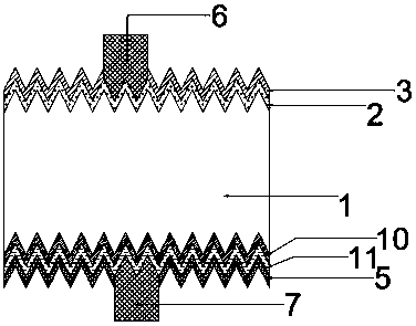
[0048] Such as image 3 , the preparation method of this n-type double-sided solar cell is as follows:

[0049] 1) Use 2%-3% KOH solution on the above-mentioned silicon substrate 1 to carry out alkali texturing at a temperature of 70-80 degrees, and use HF and HCl acid solution to clean the surface.

[0050] 2) The preparation method of the back emitter is to use thermal oxidation to grow a 1nm silicon oxide layer as a thin tunnel passivation layer 10, and then use a low-pressure vapor phase chemical deposition method to deposit a 100nm boron-doped polysilicon layer 11. After annealing, a rear hetero-emitter structure is formed. Sheet resistance is 90ohm / sq.

[0051] 3) The polysilicon deposited on the front side is removed through the back-enhanced chemical vapor deposition 100nm silicon nitride mask and 1%wt concentration of KOH alkali etching cleaning process, and the insulation treatment is completed. Cleaning using a solution containing HF acid. Then dry.

[0052] 4)...

Embodiment 3

[0058] As an example, the preparation method of this n-type double-sided solar cell is as follows:

[0059] 1) Dedamaging and cleaning the n-type silicon substrate 1 . Use NaOH solution for damage treatment, and use hydrofluoric acid, hydrochloric acid mixture for cleaning.

[0060] 2) The emitter is prepared on the back side of the silicon substrate 1 . A BBr3 tubular diffusion process is performed to prepare a pn junction on the back side of the silicon substrate 1 . Diffusion peak temperature is 970°C. The diffusion resistance is 90ohm / sq, and oxygen is introduced in the process. After the preparation of the pn junction is completed, a mask is prepared on the back side. The back mask in this embodiment is that during the BBr3 diffusion process, a large amount of oxygen 20slm is introduced in the high temperature process of the diffusion process, and the oxidation time is 90min to form borosilicate glass as mask.

[0061] 3) The front side is etched in the chain cleanin...


PUM

PropertyMeasurementUnit
Thicknessaaaaaaaaaa
Wavelengthaaaaaaaaaa

Abstract

The invention provides a preparation method of an n-shaped double-surface solar cell. Affected layer removing or texturing and cleaning are performed on an n-shaped silicon substrate; an emitting electrode is prepared on the back surface of the silicon substrate; insulating treatment is performed; a front surface field is prepared on the front surface of the silicon substrate; passivation of the light receiving surface and preparation of an anti-reflection film and preparation of a back passivation layer are performed; an electrode slurry layer including the conductive component is graphicallyformed on the front surface and the back surface; the first thermal treatment process is performed; and the second thermal treatment process is performed. The contact resistance formed by the methodis lower than the conventional method, and the surface passivation film also has better passivation performance through second thermal treatment so that the process flow is simple. Besides, the emitting electrode is arranged on the back surface of the solar cell so that preparation of the anti-reflection film of the front surface of the solar cell is not much restricted, designing of the passivation layer on the surface of the emitting electrode of the back surface does not consider the influence of the light transmittance and the optimal passivation of the back surface can be realized.

Description

technical field [0001] The invention relates to a preparation method of an n-type double-sided solar cell. Background technique [0002] At present, with the gradual depletion of fossil energy, solar cells are used more and more widely as a new energy alternative. A solar cell is a device that converts the sun's light energy into electrical energy. Solar cells use the principle of photovoltaics to generate carriers, and then use electrodes to extract the carriers, which is beneficial to the effective use of electrical energy. [0003] In the steps of solar cells currently used, a high-temperature sintering step will be carried out after the coating of the patterned conductive paste is formed. This step will cause the following problems: traditional sintering, high temperature, and harmful to the emission of the battery The passivation performance of the electrode and the back field has a greater negative impact; the traditional sintering, the contact resistance and series ...

Claims


Application Information

Patent Timeline
IPC IPC(8): H01L31/0216H01L31/0224H01L31/068H01L31/18
CPCH01L31/02167H01L31/02168H01L31/022441H01L31/0684H01L31/1804H01L31/1864H01L31/1868Y02E10/547Y02P70/50
Inventor 李华靳玉鹏
Owner TAIZHOU LERRISOLAR TECH CO LTD
Why Eureka
Try Eureka