
Multielement material collaborative gasification method and system

A gasification system and material technology, applied in the field of resource utilization of waste, can solve the problems of inability to utilize organic fluid waste, increase investment, consume large energy consumption, etc., achieve the combination of high and low energy levels, and avoid disposal Effect

Pending Publication Date: 2018-07-27
WUHAN KAIDI ENG TECH RES INST CO LTD
View PDF6 Cites 4 Cited by
  • Summary
  • Abstract
  • Description
  • Claims
  • Application Information

AI Technical Summary

Problems solved by technology

However, tar will be produced during pyrolysis, which will cause great harm to production and human health, and tar will easily produce carbon black when burned, which will cause serious damage to equipment. For example, a commonly used sludge rotary kiln Pyrolysis process, which produces a lot of tar, is easy to block pipelines, corrode equipment, etc., often shuts down for maintenance, and requires complex oil-water separation and purification devices at the back end, resulting in a significant increase in investment
[0004] The existing pyrolysis and gasification process of organic fluid waste mainly adopts external heating horizontal reactor and fluidized bed equipment. However, due to the very high water content of organic fluid waste, even the organic fluid waste after dehydration The water content of the waste is also as high as 80-90%. Therefore, there are many disadvantages in the operation process of this organic fluid waste treatment process with a high water content. Directly using organic fluid waste as raw material is prone to hardening and wall sticking in the reactor. and other phenomena, which make it difficult for the equipment to operate continuously, and the thermal conversion efficiency of organic fluid waste is not high; while using dry organic fluid waste as raw material, the pre-drying pretreatment of organic fluid waste consumes a lot of energy
[0005] In summary, the current conventional treatment methods are unable to recycle organic fluid waste and cannot meet the technical requirements for organic fluid waste treatment. Therefore, it is important to develop new technologies for resource utilization of organic fluid waste. Therefore, it is necessary to comprehensively consider environmental pollution, health safety and economic benefits, and how to completely solve the pollution problem caused by organic fluid waste is imminent.

Method used


Image

  • Multielement material collaborative gasification method and system
  • Multielement material collaborative gasification method and system
  • Multielement material collaborative gasification method and system

Examples


Embodiment 1

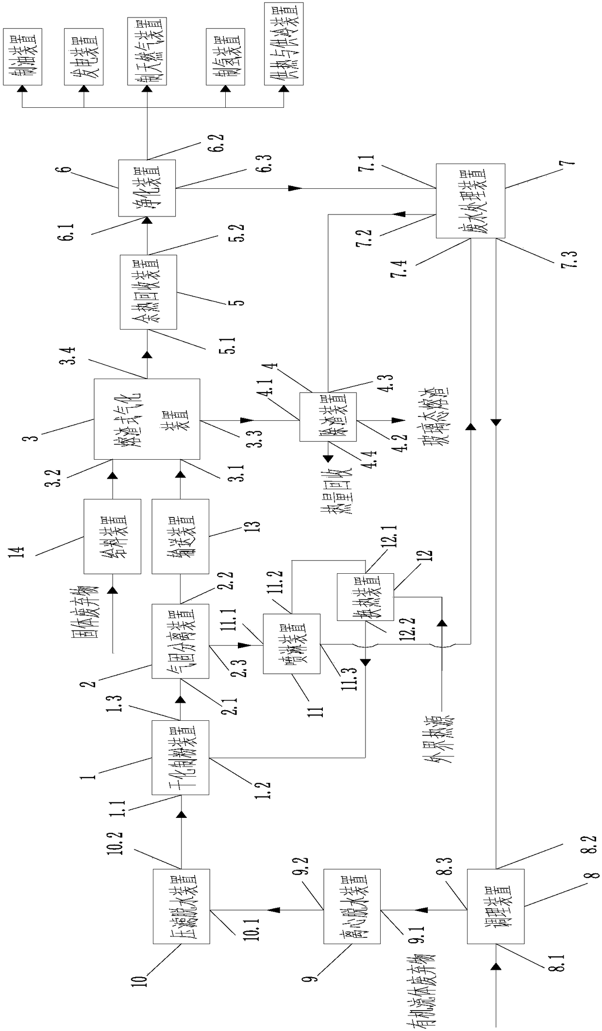
[0057] like figure 1 Shown is the multi-material collaborative gasification system of the first embodiment, including a dry pulverization device 1, a gas-solid separation device 2, a slag-type gasification device 3, a slag removal device 4, a waste heat recovery device 5, and a purification device 6. Wastewater treatment device 7 , conditioning device 8 , centrifugal dehydration device 9 , filter press dehydration device 10 , spray device 11 , and heat exchange device 12 . In this embodiment, the gas-solid separation device 2 is preferably a cyclone separator; the slag gasification device 3 is preferably a fixed bed slag gasifier, a fluidized bed slag gasifier, or a plasma slag gasifier. One; the slag removal device 4 is preferably a slag removal tank; the waste heat recovery device 5 is preferably a waste heat recovery boiler; the purification device 6 is preferably a purification tower; the conditioning device 8 is preferably a conditioning tank; the centrifugal dehydration ...

Embodiment 2

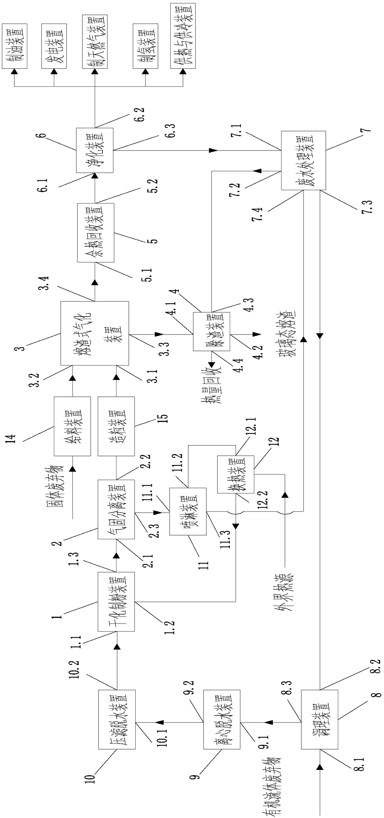
[0071] like image 3 Shown is the multi-component material collaborative gasification system of the second embodiment, including dry pulverization device 1, gas-solid separation device 2, slag-type gasification device 3, slag removal device 4, waste heat recovery device 5, and purification device 6. Wastewater treatment device 7 , conditioning device 8 , centrifugal dehydration device 9 , filter press dehydration device 10 , spray device 11 , and heat exchange device 12 . In this embodiment, the gas-solid separation device 2 is preferably a cyclone separator; the slag gasification device 3 is preferably a fixed bed slag gasifier, a fluidized bed slag gasifier, or a plasma slag gasifier. One; the slag removal device 4 is preferably a slag removal tank; the waste heat recovery device 5 is preferably a waste heat recovery boiler; the purification device 6 is preferably a purification tower; the conditioning device 8 is preferably a conditioning tank; the centrifugal dehydration d...


PUM

PropertyMeasurementUnit
particle diameteraaaaaaaaaa

Abstract

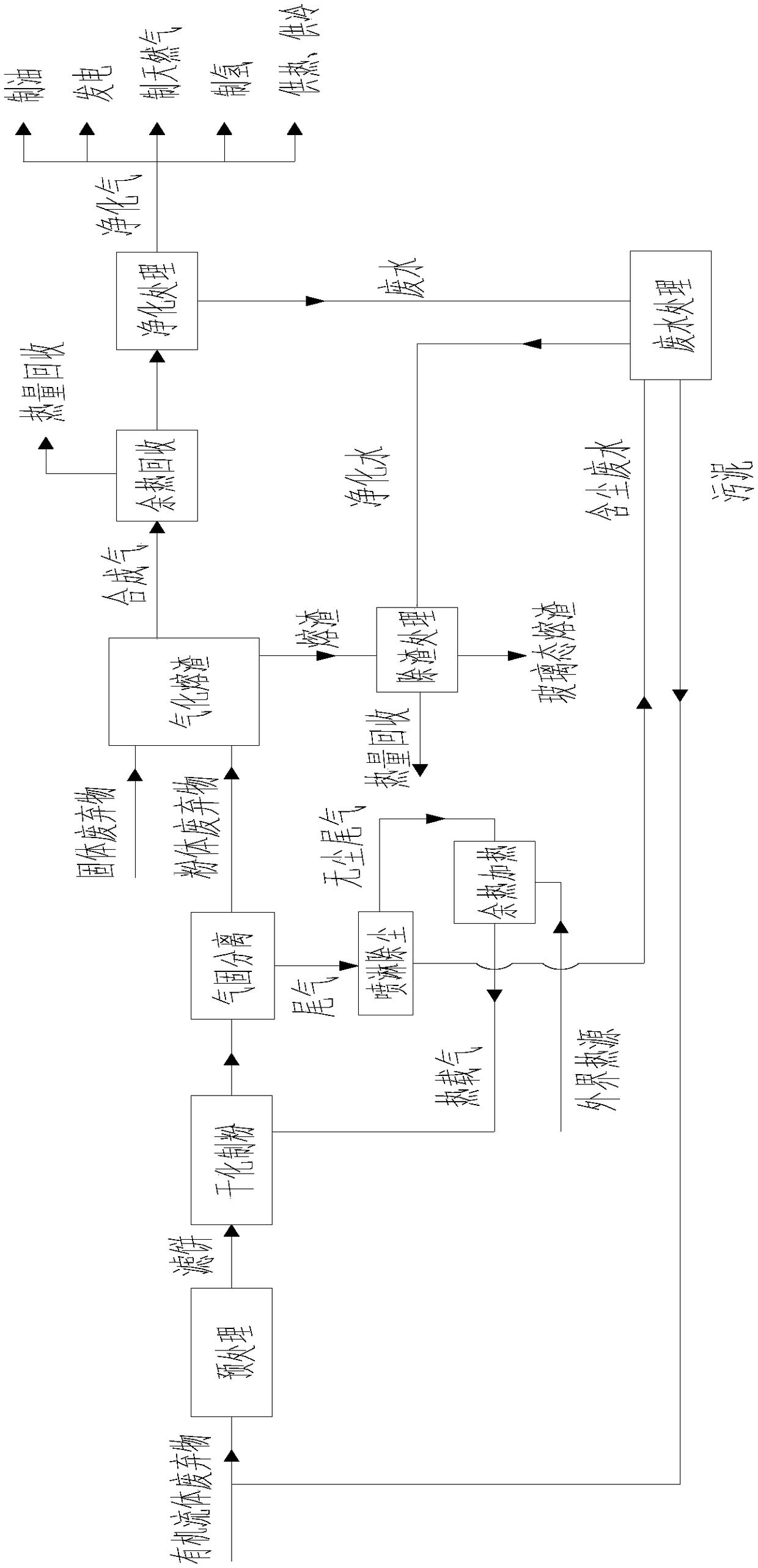
The invention discloses a multielement material collaborative gasification method and system. The method comprises the steps of 1, pretreatment, wherein pretreatment is conducted on organic fluid waste, so that filter cakes are obtained; 2, drying for powder production, wherein rotational flow heat exchange is conducted between the filter cakes and heat carrying gas, and meanwhile, crushing impacttreatment is conducted on the filter cakes, so that powder waste is obtained; 3, gas-solid separation, wherein the powder waste and tail gas are separated; 4, gasification of slag, wherein collaborative gasification treatment is conducted on the powder waste and additional solid waste, so that synthesis gas and the slag are obtained; 5, aftertreatment of the synthesis gas, wherein waste heat recovery is conducted on the synthesis gas in the first place, and then purification treatment is conducted, so that purified gas and waste water are obtained; 6, aftertreatment of the slag, wherein chilling treatment is conducted on the slag, so that a glassy-state slag material is obtained; and 7, treatment of the waste water. By means of the multielement material collaborative gasification method,drying treatment can be conducted on the organic fluid waste, and the fluid-form waste is produced into a powder waste material; the powder waste material can serve as a raw material of the gasification slag; and collaborative gasification treatment of the multielement materials, namely the solid waste and the organic fluid waste, is achieved.

Description

technical field [0001] The invention relates to resource utilization of waste, in particular to a multi-material collaborative gasification method and system thereof. Background technique [0002] At present, the disposal methods for organic fluid waste (such as sludge, kitchen waste, livestock and poultry manure, water algae, etc.) include landfill, incineration, sea discharge, agricultural use, pyrolysis, and gasification. However, the above-mentioned traditional treatment methods have some disadvantages, such as landfilling of organic fluid waste requires a large amount of land, and the seepage of toxic substances contained in organic fluid waste will affect water and soil resources; such as burning organic fluid waste, due to the Waste contains a large amount of harmful substances, and the combustion process will inevitably lead to the escape of a large number of harmful substances, such as nitrogen oxides, sulfur dioxide and dioxins, which will cause secondary pollution...

Claims


Application Information

Patent Timeline
Patent Type & Authority Applications(China)
IPC IPC(8): B09B3/00
CPCB09B3/00B09B3/40Y02W30/20
Inventor 陈义龙张岩丰张亮
Owner WUHAN KAIDI ENG TECH RES INST CO LTD
Learn More