Supercharge Your Innovation With Domain-Expert AI Agents!

Method for preparing micro fluidic chip template

A technology of microfluidic chips and templates, applied in the field of microfluidics, can solve the problems of negative impact on graphic accuracy, low repeatability, complicated operation, etc., and achieve the effects of rough surface, low cost, and simplified operation

Active Publication Date: 2018-08-03
SOUTHEAST UNIV
View PDF5 Cites 7 Cited by
  • Summary
  • Abstract
  • Description
  • Claims
  • Application Information

AI Technical Summary

Problems solved by technology

However, this method has low repeatability, complex operation, and easy to negatively affect the graphic accuracy of the channel
Therefore, the roughness of the plate has become the main obstacle to the low-cost PCB process for the fabrication of microfluidic chip templates

Method used


Image

  • Method for preparing micro fluidic chip template
  • Method for preparing micro fluidic chip template
  • Method for preparing micro fluidic chip template

Examples


preparation example Construction

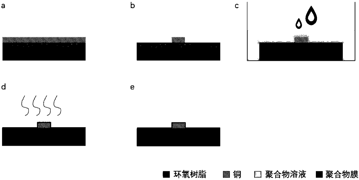
[0025] The invention discloses a preparation method of a microfluidic chip template, such as figure 1 shown, including the following steps:

[0026] S1: Making a patterned template with a rough surface using a standard printed circuit board manufacturing process, that is, using a standard printed circuit board manufacturing process to obtain a template with a rough surface but a patterned copper layer;

[0027] S2: Use the surface smoothing method based on polymer coating to planarize the rough surface of the exposed epoxy resin: soak the rough template in the polymer solution, and as the solvent volatilizes, the polymer gradually precipitates to form an attached The film on the template is used to planarize the rough surface of the epoxy resin; the solvent used in the polymer solution is a volatile solvent, including one or more of methylene chloride, chloroform, and toluene; the polymer in the polymer solution is poly Carbonate and / or polystyrene;

[0028] S3: Bake the tem...

Embodiment 1

[0030] by figure 2 The design of the microfluidic chip as an example. The dichloromethane solution of polystyrene was selected as the film-forming solution. The solution concentration is 0.2 wt.%. The baking temperature is selected as 90° C. for 1 hour. The method is used to prepare a microfluidic chip template with a height of 70 um and a minimum line width of 100 um.

[0031] Step 1. Fabricate a patterned stencil with a rough surface using a standard PCB fabrication process

[0032] FR4 glass fiber epoxy resin copper clad laminate with 2oz (70um) copper layer thickness is selected as the experimental raw material. After standard cleaning, lamination, exposure, development, copper engraving, and film removal, a printed circuit board conforming to the design drawing is produced.

[0033] Cleaning includes plasma water cleaning, ultrasonic cleaning, air knife drying, etc.

[0034] Lamination means laminating a layer of photosensitive film on the copper clad board and pre...


PUM

PropertyMeasurementUnit
Thicknessaaaaaaaaaa

Abstract

The invention discloses a method for preparing a micro fluidic chip template. The method comprises the following steps: S1) using a standard printed circuit board making technology for making a patterning template with a rough surface; S2) using a surface flattening method based on a polymer coating, and performing planarization on the rough surface of exposed epoxy resin; and S3) baking the template so that the polymer coating is tightly applied with an original template. According to the invention, cost is effectively reduced, the problem of the rough surface of a printed circuit board can be thoroughly solved, and the operation of subsequent bonding is simplified. Compared with a soft lithography making template on a silicon chip, the prepared template base material is changed from siliconand a photoresist to a glass fiber epoxy resin plate and copper, mechanical strength is greatly increased, the operation difficulty for making the chip is decreased, and the preservation conditionrequirement of the template is reduced.

Description

technical field [0001] The invention relates to the field of microfluidics, in particular to a method for preparing a microfluidic chip template. Background technique [0002] In recent years, microfluidic chip technology based on microfabrication technology has become one of the hottest cutting-edge analytical technologies due to its advantages of fast analysis speed, low reagent consumption, easy integration and high-throughput analysis. It provides a new platform for point selection, drug screening, preclinical testing and dosage determination. Microfluidic chips are generally manufactured by inversion or hot pressing. The hot-press template generally uses a high-precision metal template. The materials of the inversion template include glass, silicon, photoresist, etc. Microfluidic chips are generally fabricated in the laboratory using the inverted mold method. The production of the inverted template depends on the high-precision semiconductor processing technology, whi...

Claims


Application Information

Patent Timeline
IPC IPC(8): B01L3/00
CPCB01L3/00B01L3/502707
Inventor 王著元杨阔崔一平宗慎飞
Owner SOUTHEAST UNIV
Features
  • R&D
  • Intellectual Property
  • Life Sciences
  • Materials
  • Tech Scout
  • Unparalleled Data Quality
  • Higher Quality Content
  • 60% Fewer Hallucinations
Learn More