

Breast duct endoscope imaging probe
An imaging probe and endoscope technology, applied in endoscopy, mammography, medical science, etc., can solve the problems of limited image resolution, complex optical design, limited imaging depth of ductoscope, etc., to improve detection sensitivity and image resolution, high detection sensitivity and image resolution, the effect of reducing the difficulty of optical design
- Summary
- Abstract
- Description
- Claims
- Application Information
AI Technical Summary
Problems solved by technology
Method used
Image

Examples
Embodiment 1
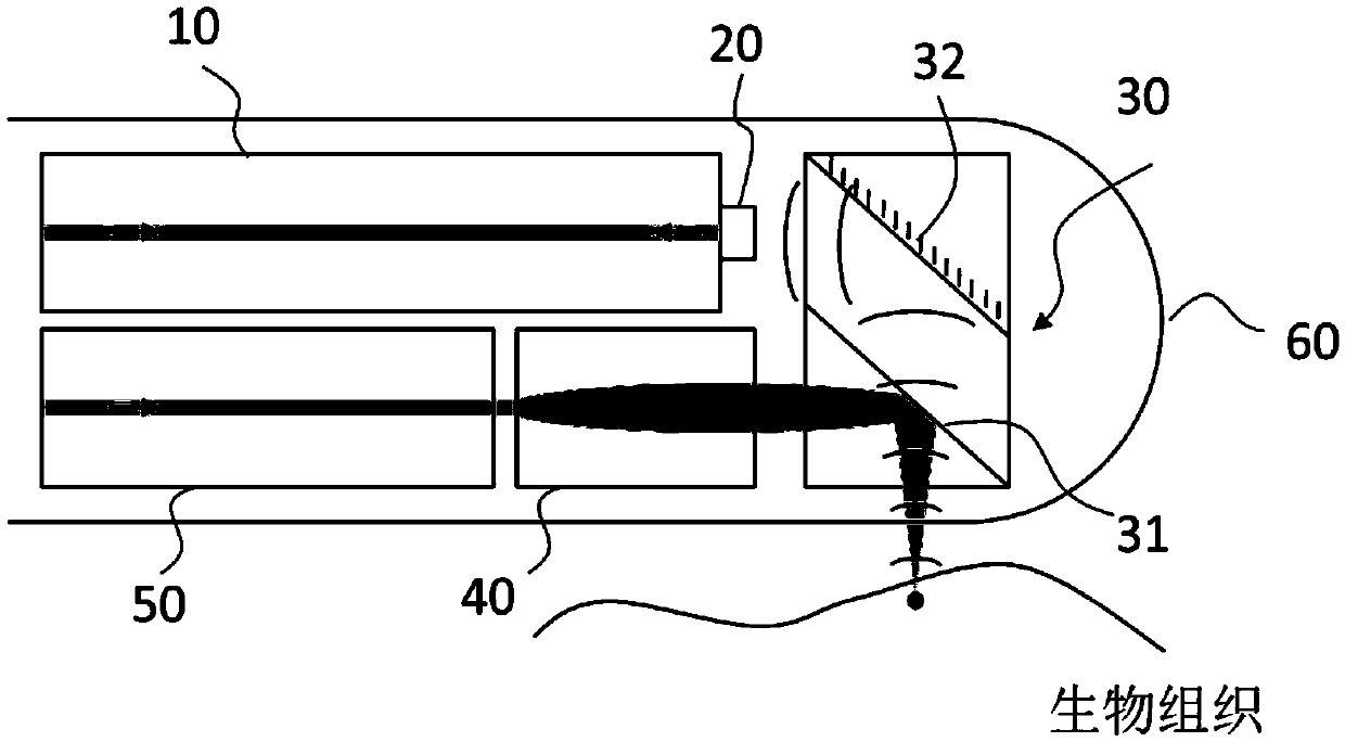
[0040] The present invention provides a breast duct endoscope imaging probe based on the principle of acousto-optic imaging, such as image 3 As shown, it includes an optical fiber, a collimating and converging element 40, a reflective element 30 and a capsule 60. The optical fiber includes an exciting optical fiber 50 and a receiving optical fiber 10. The probe also includes an optical resonance element for changing the resonance frequency under the returned ultrasonic waves. 20. The positional relationship of the excitation fiber 50, the receiving fiber 10, the collimating and converging element 40, the reflection element 30, the capsule 60 and the optical resonance element 20 satisfies the following optical path: the pulsed laser is coupled into one end of the excitation fiber 50, and the excitation fiber The other end of 50 is focused and irradiated by the collimating and converging element 40 to the first reflective surface 31 of the reflective element 30, and then reflec...
Embodiment 2
[0046] The principle and structure of this embodiment are the same as Embodiment 1, the difference is that: Image 6 As shown, the reflective element 30 includes two independent reflective mirrors; the first reflective mirror 33 is used to reflect or converge the laser output from the collimating and converging element, and has an optical reflective surface; the second reflective mirror 34 is used to reflect Or gather the reflected ultrasonic signal, with a stainless steel reflective surface.
Embodiment 3
[0048] The principle and structure of this embodiment are the same as Embodiment 1, the difference is that: Figure 7 As shown, the reflective element 30 includes an independent third reflective mirror 36 and an independent third reflective surface 35, wherein the third reflective surface 35 is used to reflect or converge the laser output from the collimating and converging element 40, which can It is the end surface or polished surface of the excitation fiber 50 with a certain angle (for example, 45 degrees); the third reflector 36 is used for reflecting or converging the reflected ultrasonic signal, and has a stainless steel reflective surface.
[0049] The reflective surface or mirror of the reflective element 30 is processed by a surface coating process.
[0050] The optical resonant element 20 may also be other optical resonant cavities with Fano resonance effect, such as photonic crystals of metal surface plasmons or reflective gratings.
PUM
 Abstract
Description
Claims
Application Information