Method and device for treating acid gas

A treatment device and treatment method technology, applied in the direction of gas treatment, separation methods, chemical instruments and methods, etc., can solve the problems of high energy consumption of amine liquid regeneration, complex production equipment, and the inability of production equipment to operate continuously for a long period, so as to reduce Energy consumption, environmental protection effect of treatment process

Active Publication Date: 2018-11-02
CHINA PETROLEUM & CHEM CORP +1
View PDF14 Cites 0 Cited by
  • Summary
  • Abstract
  • Description
  • Claims
  • Application Information

AI Technical Summary

Problems solved by technology

The two-stage Claus + tail gas hydrogenation reduction + solvent absorption technology is mature, and the quality of the product sulfur is stable. However, due to the long process, large investment, high energy consumption, high requirements for device safety control, and the Claus process can only handle high-concentration acid gases, so , this technology has no advantages for sour gas treatment in small refineries
Refinery acid gas contains H 2 In addition to S gas, it also contains a certain amount of CO 2 gas, during the production of soda sulfide, CO 2 The gas will produce Na with raw lye 2 CO 3 / NaHCO 3 Impurities cause blockage of process pipelines in the production process, resulting in the failure of long-term continuous operation of production equipment, and there are problems such as high alkali consumption and poor product purity.
[0007] Patents CN102765700A and CN102807193A disclose NaHS production process and NaHS continuous absorption reaction production device with two-stage absorption, one-stage alkali protection and one-stage adsorption process, acid gas and alkali agent adopt countercurrent absorption method, and finally the solution is evaporated, concentrated and dehydrated, cooled Molding, packaging process, to complete the generation process of NaHS, this technology is only applicable to the pure hydrogen sulfide absorption process, and does not consider CO 2 Effect of gas
CN103551018A discloses a method for purifying and recycling sulfur-containing tail gas, using barium sulfide to treat CO in the gas 2 Removed to obtain H 2 S gas can produce high-quality NaHS products, but it produces barium sulfite and barium carbonate precipitates, which are difficult to handle
Patent CN103754833A discloses a device and method for producing NaHS using refinery dry gas, using supergravity technology to perform selective desulfurization on dry gas to obtain 99% H 2 The purity of NaHS produced by S gas can reach more than 42%, but the raw material gas pretreatment process of this technology is long, the production equipment is complex, and the energy consumption of regeneration of rich absorption liquid is high
The NaHS production technology described in CN103446849A, CN103466559A and CN103638802A also faces the problems of complicated process, high energy consumption of amine liquid regeneration in acid gas pretreatment, etc.

Method used


Image

  • Method and device for treating acid gas
  • Method and device for treating acid gas

Examples


Embodiment 1

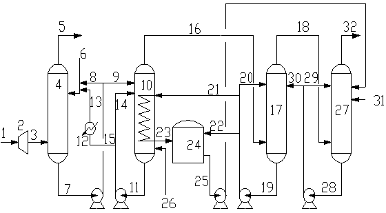
[0088] A refinery acid gas quantity Q=280Nm 3 / h, pressure 0.6Mpa, of which H 2 S volume fraction is 78%, CO 2 The volume fraction is 21%, and the remainder is hydrocarbons and other substances. use figure 1 The treatment method and device shown treat the acid gas. Wherein, the hydrate decomposer adopts a conventional tank structure with heat exchange equipment inside, and a stripping gas inlet line is provided on the shell of the hydrate decomposer.

[0089] The operating conditions and treatment effects during the treatment process are as follows: the hydrate working fluid consists of water, SDS accounting for 0.03% of the mass fraction of the aqueous solution, polyethylene glycol accounting for 8% of the mass fraction of the aqueous solution, diesel with a volume ratio of 1 / 2 to water, Composition of Span (sorbitan fatty acid ester) emulsifier with a mole ratio of 0.8% to water. The acid gas is pressurized by the compressor to 1.2Mpa and then introduced into the hydration re...

Embodiment 2

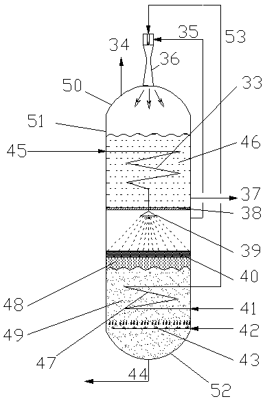
[0091] Same as Example 1, except that figure 2 In the structure of the decomposer, the volume ratio of the hydrate heating section and the hydrate dissociation and gasification section of the hydrate decomposer is 1 / 1, the liquid holding capacity in the hydrate heating section is 1 / 2 of the volume of the hydrate The liquid holding capacity of the decomposing and gasifying section is 1 / 2 of the total volume of this section. The broken baffle component in the hydrate decomposer adopts a screen structure with an average hole diameter of 5mm.

[0092] Due to the use of the present invention to provide a preferred hydrate decomposer, two-stage high-efficiency cascade heat exchange, the heat of the entire process is rationally used, and the working fluid can be decomposed (regenerated) under the same hydrate decomposing operating conditions as in Example 1. ) More complete, when the same effect as in Example 1, the amount of hydrate working fluid can be reduced to 4.6m 3 / h, reducing ...

Embodiment 3

[0094] Same as Example 2, except that the hydrate working fluid used is emulsified by water, SDS with a mass fraction of 0.03% of the aqueous solution and diesel with a volume ratio of 1 / 2 to water, and Span with a molar ratio of 0.8% to water. Agent composition.

[0095] Under the same operating conditions of the hydrate reactor as in Example 2, the CO in the tail gas treated by the hydration reactor 2 The concentration is about 70%; after the hydrate-rich working fluid is processed by the hydrate decomposer, CO in the gas 2 Concentration> 4%, increased CO 2 Form Na 2 CO 3 / NaHCO 3 The influence of other substances on the continuous and stable operation of the NaHS production unit has increased the difficulty of the long-term operation of the device.


PUM


Abstract

The invention provides a method and device for treating acid gas. The device can produce NaHS products meeting national quality standards while realizing up-to-standard discharge of the acid gas, andorganically integrates environmental governance and the production process of chemical products into an integrated process. Compared with the prior art, the method has the advantages that the acid containing CO2 gas and hydrogen sulfide gas can be economically and efficiently pretreated, energy during a technical process is reasonably utilized, energy consumption is greatly reduced, and the wholetreatment process is environmentally friendly, reliable, and free from production of three wastes.

Description

Technical field [0001] The invention relates to a method and device for processing acid gas, in particular to the purification of acid gas containing carbon dioxide and hydrogen sulfide and the recycling of pollutants. Background technique [0002] Refinery acid gas is a kind of processing tail gas produced during petroleum processing, and its main component is H 2 S and CO 2 . Refinery acid gas mainly comes from sour water stripping, circulating hydrogen desulfurization, dry gas and liquefied gas desulfurization devices. Large-scale refineries have a relatively large amount of acid gas (annual sulfur output> 5000t / a), so acid gas treatment devices for sulfur production (such as Claus process and LO-CAT process) are generally established. 2 S is recycled. For small and medium refineries (annual sulfur production <5000t / a), due to the small amount of acid gas, the cost of setting up a sulfur plant is relatively high. Most small refineries basically treat the acid gas by com...

Claims


Application Information

Patent Timeline
Patent Type & Authority Applications(China)
IPC IPC(8): B01D53/75B01D53/78B01D53/52B01D53/62
CPCB01D53/52B01D53/62B01D53/75B01D53/78B01D2257/504
Inventor 孟凡飞彭德强王海波王璐瑶陈新
Owner CHINA PETROLEUM & CHEM CORP
Why Eureka
Try Eureka