
Rotation-based combined desulfurization and denitrification distribution system

A desulfurization and denitrification, rotary type technology is applied in the field of combined desulfurization and denitrification layout system, which can solve the problems of difficult desulfurization product treatment, large ammonia escape, limited load capacity of units, etc., and achieves saving operation and maintenance costs, simple system layout, and consumption The effect of low electricity rate

Pending Publication Date: 2018-12-07
XIAN THERMAL POWER RES INST CO LTD
View PDF0 Cites 2 Cited by
  • Summary
  • Abstract
  • Description
  • Claims
  • Application Information

AI Technical Summary

Problems solved by technology

[0003] At present, coal-fired power plant boilers generally use limestone / gypsum wet desulfurization technology (FGD) and selective catalytic reduction denitrification technology (SCR) to reduce SO in coal-fired flue gas. 2 , NOx removal, this technical solution is relatively mature, but there are also the following problems: FGD system investment and operation and maintenance costs are high, there are problems such as system fouling, equipment corrosion, etc. In addition, the power consumption rate of the desulfurization system is relatively high, and the desulfurization products Faced with difficult problems, such as desulfurization wastewater generated during the desulfurization process, separate desulfurization wastewater treatment facilities must be set up
After the catalytic performance of the denitrification system catalyst declines, coal-fired power plant boilers have to adopt excessive ammonia injection in order to meet the NOx at the outlet of the denitrification system within the standard range, resulting in a large amount of ammonia escape from the denitrification system. Medium SO 3 1. Water vapor reacts to generate ammonium bisulfate, and the flue gas containing ammonium bisulfate exists in liquid form when it flows through the air preheater, and is firmly bonded to the surface of the heat storage element of the air preheater, causing serious clogging of the air preheater , the load capacity of the unit is limited

Method used


Image

  • Rotation-based combined desulfurization and denitrification distribution system
  • Rotation-based combined desulfurization and denitrification distribution system

Examples


Embodiment Construction

[0028] The present invention will be further described in detail below in conjunction with the accompanying drawings.

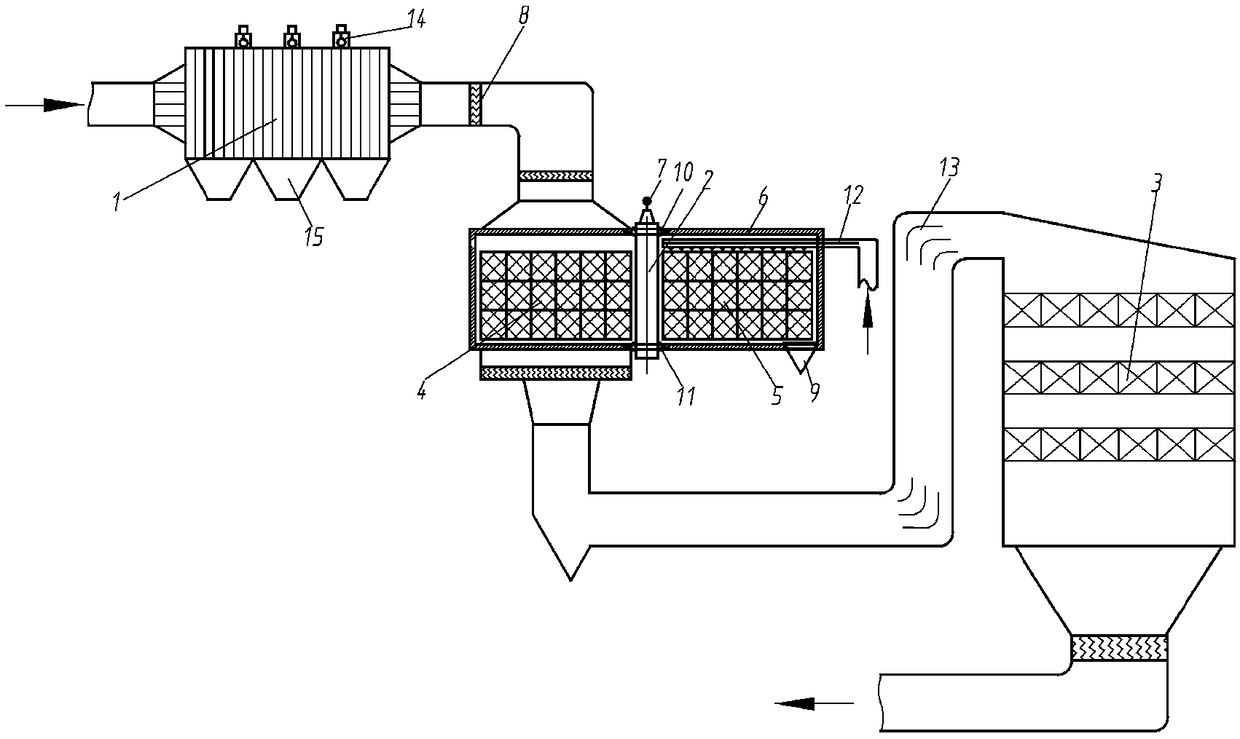
[0029] see figure 1 , The present invention proposes a new type of combined desulfurization and denitration system, the main features of which are: (1) A high-temperature electrostatic precipitator and a desulfurization device are arranged in front of the SCR denitration device, which can prevent ammonia escape from the SCR denitration device and SO2 2 The reaction generates ammonium hydrogen sulfate, which effectively solves the problems of air preheater, low and low temperature economizer, and induced draft fan equipment corrosion and ash blocking, and ensures long-term efficient and stable operation of the unit. (2) Activated carbon fibers adsorb SO in oxygen atmosphere 2, NO experimental results show that activated carbon fibers have poor adsorption capacity for NO, but NO helps activated carbon fibers to absorb SO. 2 Gas adsorption, within 90 minutes o...


PUM


Abstract

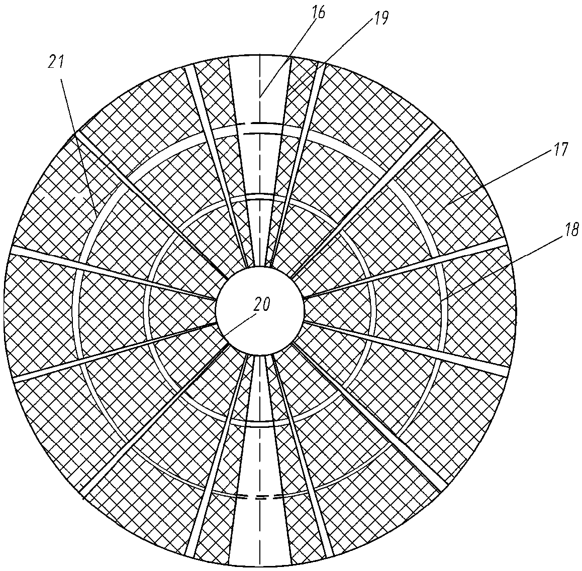
The invention relates to a rotation-based combined desulfurization and denitrification distribution system. The system comprises a rotation type dry desulfurization and adsorbent regeneration device,wherein the rotation type dry desulfurization and adsorbent regeneration device comprises a shell, an adsorption bin and a regeneration bin are formed in the shell, a first rotation bin box containingan absorbent is mounted in the adsorption bin, a second rotation bin box containing an absorbent is mounted in the regeneration bin, a hollow rotating shaft is arranged between the first rotation binbox and the second rotation bin box, and the first rotation bin box and the second rotation bin box can rotate along the hollow rotating shaft; and a high-temperature electric dust remover is connected with the adsorption bin, and the adsorption bin is connected with a selective catalytic reduction denitrification device. The high-temperature electric dust remover and the denitrification device are distributed in front of an SCR device, so that the content of dust in the dust entering the SCR device is effectively controlled, SO2 in the smoke is completely removed, and ammonium hydrogen sulfate is not generated even when the escape amount of ammonia at an outlet of an SCR system is great.

Description

technical field [0001] The invention belongs to the field of boiler environmental protection, and in particular relates to a combined desulfurization and denitrification arrangement system based on a rotary type. Background technique [0002] Sulfur oxides and nitrogen oxides are the main air pollutants in coal-fired power station boilers. In recent years, with the large-scale implementation of environmental protection transformation, SO 2 and NOx have been effectively controlled. At present, it is required that newly built units should simultaneously build advanced and high-efficiency desulfurization, denitrification and dust removal facilities. The newly built units in the eastern region basically meet the gas turbine emission limit, the central region is close to or reaches the gas turbine emission limit in principle, and the western region is encouraged to approach or reach the gas turbine emission limit. limit. At the same time, we will steadily push forward the envir...

Claims


Application Information

Patent Timeline
IPC IPC(8): B01D53/86B01D53/56B01D53/90B03C3/02B01D53/06
CPCB01D53/06B01D53/8631B01D53/90B03C3/02B01D2259/40083B01D2258/0283B01D2257/302
Inventor 杨辉何未雨党黎军张宇博陆军张海龙
Owner XIAN THERMAL POWER RES INST CO LTD
Learn More