Liquid-drop microfluidic chip for separation of single cells and preparation method for liquid-drop microfluidic chip

A single-cell separation and microfluidic chip technology, applied in the field of droplet microfluidic chips and their preparation, can solve the problems of cell damage, low capture efficiency, cumbersome and complicated operation steps, etc. Wide range of effects

Pending Publication Date: 2018-12-07
DALIAN INST OF CHEM PHYSICS CHINESE ACAD OF SCI
View PDF3 Cites 19 Cited by
  • Summary
  • Abstract
  • Description
  • Claims
  • Application Information

AI Technical Summary

Problems solved by technology

[0006] The purpose of the present invention is to provide a droplet microfluidic chip for single-cell separation and its preparation method, so as to solve the limitations of cumbersome and complicated operation steps

Method used


Image

  • Liquid-drop microfluidic chip for separation of single cells and preparation method for liquid-drop microfluidic chip
  • Liquid-drop microfluidic chip for separation of single cells and preparation method for liquid-drop microfluidic chip
  • Liquid-drop microfluidic chip for separation of single cells and preparation method for liquid-drop microfluidic chip

Examples


Embodiment 1

[0046] Preparation of superstructure SU-8 template for droplet microfluidic chip for single cell separation

[0047] The microfluidic chip uses photolithography and etching methods to prepare the SU-8 template with the protruding part of the channel; first, a layer of SU-8 glue with a thickness of 100 μm is thrown on the silicon wafer, and it is baked at 95 °C for 20 minutes, and then cooled naturally. The film was placed on the SU-8 glue plate, exposed to UV light for 30s, baked at 95°C for 20min, and cooled naturally; the SU-8 glue was developed with ethyl lactate for 10min, hardened at 180°C for 2h, and cooled naturally for use.

Embodiment 2

[0049] Preparation of a substructure SU-8 template for a droplet microfluidic chip for single-cell separation

[0050] First, throw a layer of SU-8 glue on the silicon wafer with a thickness of 150μm, bake at 95°C for 30min, cool down naturally, place the mask on the SU-8 glue plate, expose to UV for 45s, bake at 95°C for 30min, naturally Cool down; use ethyl lactate to develop the above-mentioned SU-8 glue for 10 minutes, harden the film at 180°C for 2 hours, and cool down naturally for use.

Embodiment 3

[0052] Preparation of PDMS chips for single cell isolation

[0053] The PDMS and the initiator were mixed uniformly at a volume ratio of 10:1, poured into the two SU-8 templates prepared in the previous stage, cured in an oven at 80 °C for 30 min, and the PDMS and SU-8 templates were peeled off to obtain the upper and lower layers with structures. Chip; cut the upper PDMS chip into transparent square pits along the edge of the liquid storage tank, and use a puncher to punch holes at the inlet of the dispersed phase and the inlet of the continuous phase; the upper and lower layers of the chip are treated with plasma for 120s, and the key Co-sealing spare.

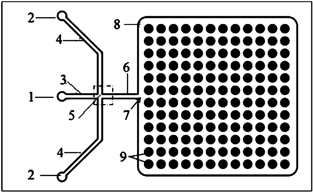
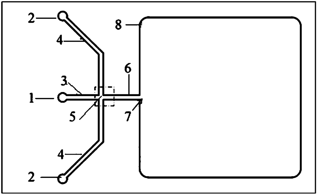
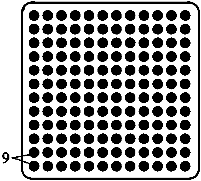
[0054] The aqueous single cell suspension of the chip flows through the dispersed phase inlet channel 3 from the dispersed phase inlet 1, the oil phase liquid flows through the continuous phase inlet channel 4 from the continuous phase inlet 2, and the two-phase liquid intersects the cross channel 5. Convergence, when the flu...


PUM


Abstract

The invention provides a liquid-drop microfluidic chip for separation of single cells and a preparation method for the liquid-drop microfluidic chip. The chip consists of two layers, i.e., an upper layer and a lower layer, wherein the upper layer is a liquid drop generating unit, and the lower layer is a liquid drop trapping unit; and the liquid drop generating unit is provided with structures asfollows: a dispersed phase inlet (1), a continuous phase inlet (2), a dispersed-phase liquid inlet passage (3), a continuous-phase liquid inlet passage (4), a liquid drop generating cross passage (5),a liquid outflow passage (6), a liquid outlet (7) and a liquid storage tank (8). According to the chip, an SU-8 chip template with partial-bulging passages is prepared by adopting a photoetching andcorroding method and is subjected to stripping by polydimethylsiloxane (PDMS), thereby obtaining a PDMS chip. The chip has the flexible liquid drop generating unit and has the high-pass single-cell trapping unit; and the chip is simple in structure, convenient in operation, high in efficiency, low in consumption of cells and reagents and extensive in range of application.

Description

technical field [0001] The invention belongs to the fields of microfluidic technology and the processing and fabrication of polymer chips, in particular to a droplet microfluidic chip used for single cell separation and a preparation method thereof. Background technique [0002] The microfluidic chip laboratory was devoted to the research of chip electrophoresis in the early days, and proposed the concept of micro-total analysis system (μ-TAS). In recent years, a new branch-discontinuous flow microfluidic system, the droplet microfluidic system, has emerged in the field of microfluidic chips. Droplet microfluidic systems use immiscible two-phase fluids to form droplets at the interface of microchannels, and the volume of such droplets is usually in the range of nanoliters to picoliters (10 liters). -9 ~10 -12 L) range. Compared with continuous flow systems, droplets have the characteristics of small size, low diffusion, no cross-contamination, fast reaction kinetics, etc....

Claims


Application Information

Patent Timeline
IPC IPC(8): B01L3/00C12M1/00C12M3/00
CPCC12M23/16B01L3/5027
Inventor 秦建华张晓庆姜雷苏文涛
Owner DALIAN INST OF CHEM PHYSICS CHINESE ACAD OF SCI
Why Eureka
Try Eureka