Single cell separation method based on droplet micro-fluidic chips

A microfluidic chip and single cell separation technology, applied in the field of microfluidic technology and cell biology, can solve the problems of cumbersome and complicated operation steps, low capture efficiency, cell damage, etc., and achieve a wide range of applications, less dosage, The effect of experimenting cheaply

Pending Publication Date: 2018-12-07
DALIAN INST OF CHEM PHYSICS CHINESE ACAD OF SCI
View PDF7 Cites 24 Cited by
  • Summary
  • Abstract
  • Description
  • Claims
  • Application Information

AI Technical Summary

Problems solved by technology

[0006] The purpose of the present invention is to provide a single-cell separation method based on droplet microfluidic chip, in order to solve the limitations of cumbersome and co

Method used


Image

  • Single cell separation method based on droplet micro-fluidic chips
  • Single cell separation method based on droplet micro-fluidic chips
  • Single cell separation method based on droplet micro-fluidic chips

Examples


Embodiment 1

[0052] Preparation of a Droplet Microfluidic Chip for Single Cell Separation

[0053] Preparation of the superstructure SU-8 template of the chip: The microfluidic chip adopts photolithography and etching to prepare the SU-8 template with the channel part protruding; first, cast a layer of SU-8 glue on the silicon wafer with a thickness of 100 μm, Pre-bake at 95°C for 20 minutes, cool down naturally, place the mask on the SU-8 plastic plate, expose to ultraviolet light for 30s, bake at 95°C for 20 minutes, and cool down naturally; use ethyl lactate to develop the above SU-8 glue for 10 minutes, harden at 180°C Membrane for 2 hours, and cool down naturally for later use.

[0054] The preparation of the SU-8 template for the lower structure of the chip: First, cast a layer of SU-8 glue on the silicon wafer, with a thickness of 150 μm, pre-bake at 95°C for 30 minutes, cool down naturally, and place the mask on the SU-8 glue plate. UV exposure for 45s, post-bake at 95°C for 30min...

Embodiment 2

[0056] Preparation of PDMS chip for single cell isolation

[0057]Mix PDMS and initiator uniformly at a volume ratio of 10:1, cast on the two SU-8 templates prepared earlier, cure in an oven at 80°C for 30 minutes, and peel off the PDMS and SU-8 templates to obtain the upper chip and the lower layer with structures Chip; cut the upper PDMS chip into a transparent square pit along the edge of the reservoir, and punch holes at the inlet of the dispersed phase and the inlet of the continuous phase with a puncher; the upper and lower layers of the chip with the structure side are treated with plasma for 120s, bonded Sealed for spare.

Embodiment 3

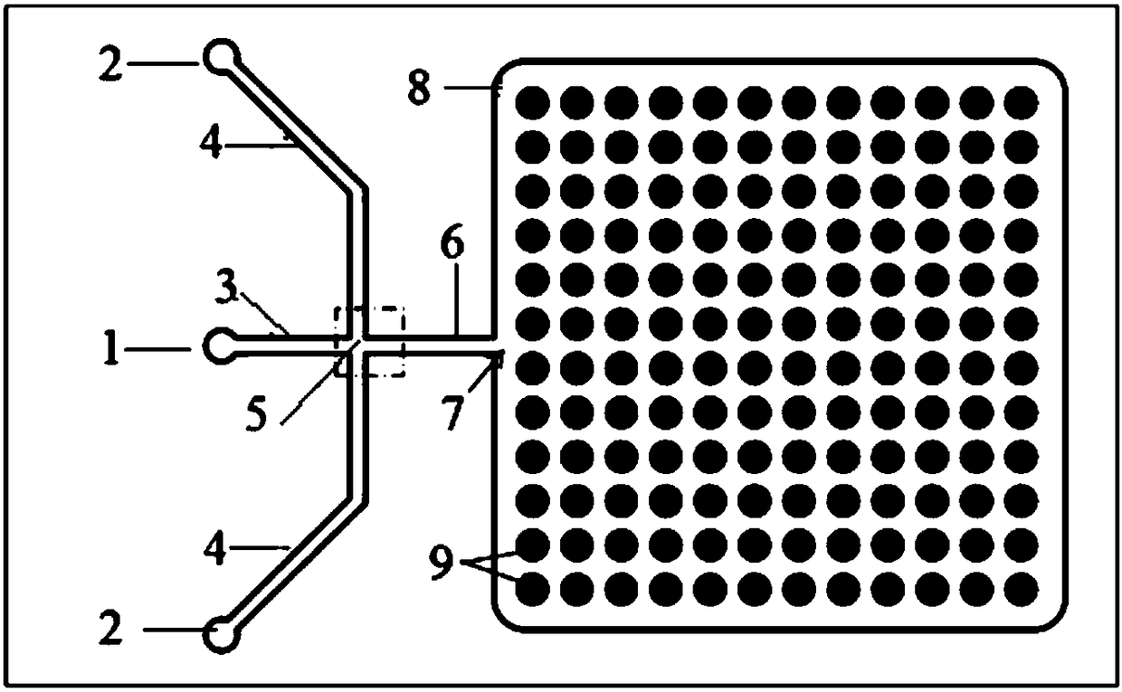
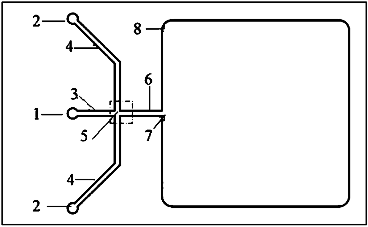
[0059] The density of single cell suspension is 10 4 cells / mL, the chip automatically captures single-cell experiments

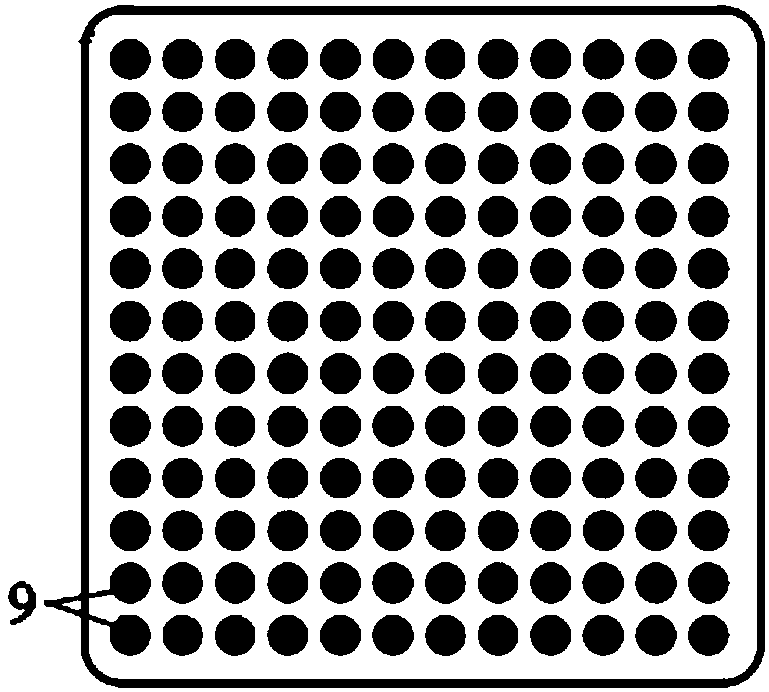
[0060] The microfluidic chip prepared above was soaked in 75% ethanol and sterilized by ultraviolet irradiation for 1 h. Subsequently, the single-cell suspension of human glioma cells (U87) was mixed with 10 4 The cell density of cells / mL flows from the dispersed phase inlet 1 through the dispersed phase liquid inlet channel 3 at a flow rate of 1 μL / min; the mineral oil containing 3% (w / w) span80 flows from the continuous phase inlet 2 through the continuous phase liquid inlet Channel 4, the flow rate is 3.5 μL / min, the two-phase liquid converges at the intersection of cross channel 5, the single cell suspension is cut into water-in-oil droplets by mineral oil; single cells are trapped in the droplets, and the droplets pass through the liquid outflow channel 6. Flow into the liquid storage tank 8 from the liquid outlet 7; with the generation of a large numb...


PUM

PropertyMeasurementUnit
Diameteraaaaaaaaaa
Cell densityaaaaaaaaaa

Abstract

The invention provides a single cell separation method based on droplet micro-fluidic chips. The method concretely comprises the following steps: A, a single cell suspension flows into a dispersed phase inlet channel from a dispersed phase inlet; B, an oil phase liquid flows into a continuous phase inlet channel from a continuous phase inlet; C, the above two phases merge to form droplets enclosing single cells, the droplets flow over a droplet capturing unit with the generation of a large number of droplets in a liquid storage pool, and stand for 2-5 min, and the superfluous droplets are sucked out when the droplets slowly settle into the droplet capture unit; and D, the droplet chips which capture the single cells are cultured in a 37 DEG C incubator, then DAPI is added to carry out nuclear staining, and the single cell capture rate is detected. The method has the advantages of simplicity and rapidity in operation, small use amounts of the cells and reagents, low experiment cost, high integration and wide application range.

Description

technical field [0001] The invention belongs to the field of microfluidic technology and cell biology, and in particular relates to a single cell separation method based on a droplet microfluidic chip. Background technique [0002] The microfluidic chip laboratory integrates the basic operation units such as sample preparation, reaction, separation, detection, cell culture, separation, and division involved in the fields of chemistry and biology into a chip of several square centimeters (or even smaller). , a technology platform that forms a network of microchannels and runs through the entire system with controllable fluids to replace various functions of conventional chemical and biological laboratories. The basic feature and biggest advantage of microfluidic chips are the flexible combination and large-scale integration of various unit technologies on an overall controllable micro platform. High-throughput is a form of scale integration, but the operational units or grou...

Claims


Application Information

Patent Timeline
IPC IPC(8): C12M1/00C12N5/00
CPCC12M23/16C12N5/00
Inventor 秦建华张晓庆姜雷苏文涛
Owner DALIAN INST OF CHEM PHYSICS CHINESE ACAD OF SCI
Why Eureka
Try Eureka