Method for forming amorphous carbon film on surface of plastic substrate

A plastic substrate, amorphous carbon film technology, applied in metal material coating process, ion implantation plating, coating and other directions, can solve the problems of easy failure of a-C film, poor plastic surface adhesion, peeling, etc., to improve the function The effect of chemical protection applications

Active Publication Date: 2018-12-18
NINGBO INST OF MATERIALS TECH & ENG CHINESE ACADEMY OF SCI
View PDF4 Cites 3 Cited by
  • Summary
  • Abstract
  • Description
  • Claims
  • Application Information

AI Technical Summary

Problems solved by technology

However, the plastic is soft and tough, while the amorphous carbon film is a ceramic material with high hardness and brittleness. There is a big difference between the two in terms of mechanical properties. It is this difference that makes it easier for the a-C film to deposit on the surface of the plastic substrate. As a result, the bonding force between the plastic surface and the a-C film is poor, and the a-C film is prone to cracks and peeled off from the substrate. Under the action of external force, the a-C film is prone to failure and cannot exert its excellent protective performance

Method used


Image

  • Method for forming amorphous carbon film on surface of plastic substrate
  • Method for forming amorphous carbon film on surface of plastic substrate
  • Method for forming amorphous carbon film on surface of plastic substrate

Examples


Embodiment 1

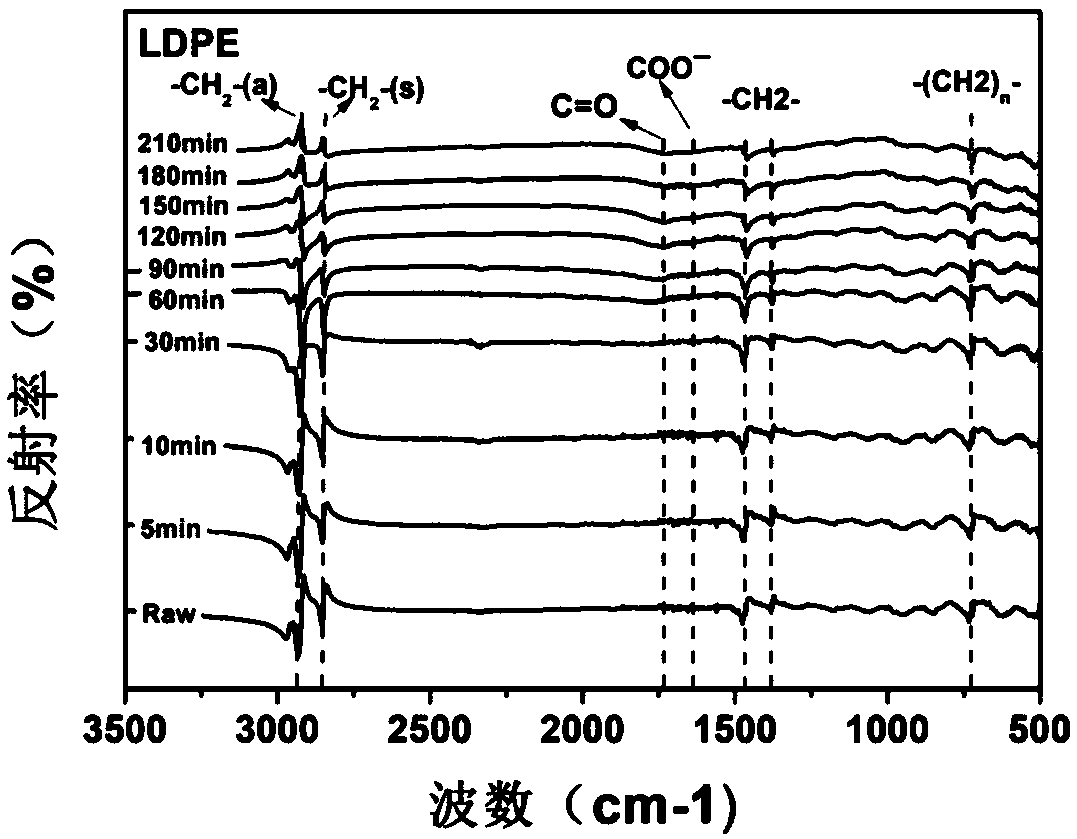
[0029] (1) The plastic matrix material is low-density polyethylene (LDPE). Grind and polish the purchased disc-shaped LDPE substrate with a diameter of 12mm and a thickness of 2mm with sandpaper, remove the burrs around the sample, and pre-clean it with a detergent, dry it naturally, and then ultrasonically clean it with absolute ethanol for 5-15 minutes, and dry it naturally stand-by;

[0030] (2) Fix the cleaned and dried LDPE substrate sample on the turret in the vacuum deposition chamber of the deposition equipment; use an ohmmeter to detect the insulation between the turret and the base surface of the vacuum chamber, and the carbon target and the base surface of the vacuum chamber; The vacuum degree of the inner foundation is less than 5.0×10 -3 Pa;

[0031] (3) Turn on the turret to rotate counterclockwise, pass in argon gas of 30-60 sccm, turn on the anode layer ion beam source, its working voltage is 500-1500V, argon plasma is generated by argon glow discharge, turn ...

Embodiment 2

[0035] (1) The plastic matrix material is ultra-high molecular weight polyethylene (UHMWPE). The disc-shaped UHMWPE plastic substrate with a diameter of 12mm and a thickness of 2mm was polished with sandpaper to remove the burrs around the sample, and pre-cleaned with a detergent. dry and ready to use;

[0036] (2) Fix the cleaned and dried UHMWPE substrate sample on the turret in the vacuum deposition chamber of the deposition equipment; use an ohmmeter to test the insulation between the turret and the base surface of the vacuum chamber, and the carbon target and the base surface of the vacuum chamber; The vacuum degree of the inner foundation is less than 5.0×10 -3 Pa;

[0037] (3) Turn on the turret to rotate counterclockwise, pass in argon gas of 30-60 sccm, turn on the anode layer ion beam source, its working voltage is 500-1500V, argon plasma is generated by argon glow discharge, turn on the bias power supply, the bias voltage 300~1200V, argon plasma pretreats the sur...


PUM

PropertyMeasurementUnit
thicknessaaaaaaaaaa

Abstract

The invention discloses a method for forming an amorphous carbon film on the surface of a plastic substrate. Firstly, the surface of the plastic substrate is pretreated by an argon plasma under the electric field effect to realize surface activation of the plastic substrate, then the surface of the plastic substrate is subjected to continuous sputtering bombarding through a carbon plasma, and gradual conversion from an organic structure on the surface of the plastic substrate to an inorganic structure is achieved by controlling the carbon plasma bombardment time. The amorphous carbon film having good binding force with the substrate is formed, and the functionalized protective application of the amorphous carbon film to the plastic substrate is improved.

Description

technical field [0001] The invention belongs to the technical field of surface engineering, in particular to a method for forming an amorphous carbon film on the surface of a plastic substrate. Background technique [0002] Due to its rich materials and various types, plastics have low density (only 1 / 7 to 1 / 8 of steel), high specific strength, excellent electrical insulation, good corrosion resistance, easy processing, low production cost, and wide range of uses. Advantages, has become an indispensable material in people's daily life. However, plastic has its disadvantages that cannot be ignored, such as: its poor wear resistance, susceptibility to environmental aging, poor thermal stability, poor hydrophilicity, etc., which seriously limit its practical application. [0003] Amorphous carbon (a-C) film has high hardness, high thermal conductivity, excellent tribological properties, low dielectric constant, good optical permeability, good chemical inertness and excellent b...

Claims


Application Information

Patent Timeline
Patent Type & Authority Applications(China)
IPC IPC(8): C23C14/02C23C14/06C23C14/35
CPCC23C14/022C23C14/0605C23C14/35
Inventor 王永欣管文曾志翔王立平薛群基
Owner NINGBO INST OF MATERIALS TECH & ENG CHINESE ACADEMY OF SCI
Why Eureka
Try Eureka