Continuous carbon fiber recovering method and continuous carbon fiber recovering device

A technology for recycling carbon fibers and carbon fibers, applied in the field of continuous carbon fiber recycling devices, can solve the problems of difficult recycling of catalysts, waste of resources, recycling costs, and damage to the mechanical properties of carbon fibers, reducing heat transfer and reaction time, improving carbon fiber recovery rates, The effect of maintaining mechanical properties

Active Publication Date: 2019-01-15
陈亮广
View PDF18 Cites 5 Cited by
  • Summary
  • Abstract
  • Description
  • Claims
  • Application Information

AI Technical Summary

Problems solved by technology

The pyrolysis method is to place waste carbon fiber reinforced composite materials under the condition of no oxygen (CN 103665427 A, CN 107345000 A) or low oxygen (CN103665430 A, CN 107417963 A) and utilize high-temperature thermal decomposition method. The process operation is simple, but the recovery can be The carbon fiber surface of the waste carbon fiber is easy to accumulate carbon, so that the carbon fiber is distributed in a block shape, which seriously affects the reuse performance; utilize a layer of solid super acid SO42-/TiO2 powder (CN 106957451 A) on the surface of the waste carbon fiber resin matrix composite material or the main component is Zinc chloride powder (CN 106807425 A) and other catalysts are placed in a pyrolysis furnace to fully react at high temperature to obtain carbon fibers with high mechanical property retention and recovery. However, after the pyrolysis reaction, the catalyst is difficult to recycle. Or the recycling process is complex, resulting in waste of resources and increased recycling costs. At the same time, the method of laying powder catalyst on the surface is more suitable for batch pyrolysis devices, and the production is discontinuous
[0006] And traditional fluidized bed recovery technology ((Plastics, Rubber and Composites, 2002,31 (6): 278-282; Applied Surface Science, 2008, 254: 2588-2593; CN 104513406 A) utilizes air as fluidizing gas to make The carbon fiber composite material is suspended in the bed, and the matrix is ​​thermally cracked to obtain recycled carbon fibers with a clean surface, no carbon

Method used


Image

  • Continuous carbon fiber recovering method and continuous carbon fiber recovering device
  • Continuous carbon fiber recovering method and continuous carbon fiber recovering device
  • Continuous carbon fiber recovering method and continuous carbon fiber recovering device

Examples


Example Embodiment

[0083] Example 1

[0084] The selected waste carbon fiber reinforced resin-based composite material is a composite of T300-3K twill woven fabric and epoxy resin from Toray, and the carbon fiber content is 60%;

[0085] Weigh 500g small pieces of waste carbon fiber reinforced resin-based composite material with a thickness of 3mm and not greater than 25×25mm, and put them into the first feeding device 15;

[0086] The SO with a particle size of 0.8mm 4 2- / ZrO 2 The solid super acid particles are placed in the second feeding device 17.

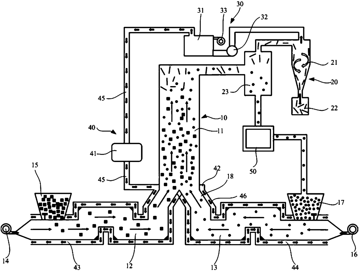
[0087] Step (1): Air is blown into the high temperature burner 31 through the third blower 33, the air heated to 1000°C is cooled to 450°C by the heat exchanger 41 and then enters the main interlayer 42, and then enters the first interlayer 43 and respectively. In the second interlayer 44, the lower end of the thermal cracking furnace 11 is heated, the first preheating pipe 12 and the second preheating pipe 13 are preheated, and the first blower 14 and...

Example Embodiment

[0090] Example 2

[0091] This embodiment is basically the same as the above embodiment 1, the difference is that the solid super acid particles used are WO 3 / ZrO 2 .

Example Embodiment

[0092] Example 3

[0093] The selected waste carbon fiber reinforced resin-based composite material is a composite of T600S-24K twill woven fabric and polyester resin from Toray, in which the carbon fiber content is 65%;

[0094] Weigh 500g of scrap carbon fiber reinforced resin-based composite material with a thickness of 3mm and no more than 45×45mm, and put it into the first feeding device 15;

[0095] MoO with a particle size of 2mm 3 / ZrO 2 The solid super acid particles are placed in the second feeding device 17.

[0096] Step (1): Blow air into the high temperature burner 31 through the third blower 33. The air heated to 1350°C is cooled to 350°C by the heat exchanger 41 and then enters the main interlayer 423, and then enters the first interlayer 43 and In the second interlayer 44, heating the lower end of the thermal cracking furnace 11, and simultaneously turning on the first blower 14 and the second blower 16 to preheat the air in the first preheating tube 12 and the second...


PUM

PropertyMeasurementUnit
Particle sizeaaaaaaaaaa
Tensile strengthaaaaaaaaaa

Abstract

The invention discloses a continuous carbon fiber recovering method comprising the following steps: step S10, heating the lower end of a thermal cracking hearth by heated air or high temperature fluegas generated from cracking reaction, and preheating a first preheating tube and a second preheating tube; step S20, blowing a waste carbon fiber reinforced resin-based composite material into the thermal cracking hearth by the first preheating tube, and at the same time, blowing solid superacid particles into the thermal cracking hearth via the second preheating tube; and step S30, merging the waste carbon fiber reinforced resin-based composite material and the solid superacid particles in the thermal cracking hearth and carrying out contact reaction, separating generated organic gas with carbon fibers in a cyclone separator to recover the carbon fibers, allowing the organic gas to enter a high temperature burner through an induced draft fan, and burning. A solid superacid is used for replacing fluidized sand particles, and the feeding and preheating methods are improved, so that the resin matrix is uniformly heated and catalytically decomposed, and thus the carbon fiber resources arerecovered and reused.

Description

technical field [0001] The invention relates to the technical field of carbon fiber recovery from waste carbon fiber reinforced composite materials, in particular to a continuous carbon fiber recovery method and a continuous carbon fiber recovery device used in the method. Background technique [0002] Carbon fiber is a new type of high-strength, high-modulus fiber material with a carbon content of more than 95%. Carbon fiber is composited with a matrix such as resin, metal, and ceramics to form a structural material called Carbon Fiber Reinforced Polymer (Carbon Fiber Reinforced Polymer, CFRP). [0003] Carbon fiber reinforced composite materials have excellent properties such as light weight, high strength, good heat resistance and corrosion resistance, and are widely used in aerospace, sports equipment, medical equipment, transportation, electronic appliances, wind power industry and other fields. An irreplaceable important strategic material. With the rapid expansion o...

Claims


Application Information

Patent Timeline
IPC IPC(8): C08J11/00C08J11/16
CPCC08J11/00C08J11/16Y02W30/62
Inventor 陈亮广
Owner 陈亮广
Why Eureka
Try Eureka