A programmable high-efficiency laser pump source module

A laser-pumped, high-efficiency technology, applied in lasers, laser components, phonon exciters, etc., can solve the problems of lower output current stability, overall efficiency drop, and lack of over-current protection, so as to prevent repeated actions , the effect of improving safety

Inactive Publication Date: 2020-05-22
JILIN UNIV
View PDF11 Cites 0 Cited by
  • Summary
  • Abstract
  • Description
  • Claims
  • Application Information

AI Technical Summary

Problems solved by technology

In this loop, the sum of the voltage drop borne by the power transistor Q1, the voltage drop borne by the sampling resistor Rs1, and the voltage drop borne by the laser diode is equal to the power supply voltage VCC (fixed value), when the set driving current changes from large to small , the voltage at both ends of the laser diode and the voltage at both ends of the sampling resistor Rs1 are correspondingly reduced, and the power transistor Q1 is a nonlinear device, which will actively bear the excess voltage to keep the sum of the three voltages equal to VCC, which will cause the circuit The generated electric power is more converted into the tube consumption of the power tube Q1, that is to say, as the set driving current decreases, the output power of the power control module decreases, but the power loss of the power control module itself increases, which means On the one hand, the overall efficiency of the system will drop sharply. On the other hand, with the increase of the tube consumption of the power tube Q1, the heat generated by it will increase, and the temperature of the system will increase, and the increase of temperature will bring about more serious problems. Consequences: Reduce the stability of the output current and bring the risk of burning out the power tube
[0005] In addition, patent 2016108010570 does not have the function of overcurrent protection. Once a certain control unit fails and the current value output to the butterfly laser module exceeds the maximum safe current value that the butterfly laser can withstand, it is easy to burn the butterfly laser. Bad

Method used


Image

  • A programmable high-efficiency laser pump source module
  • A programmable high-efficiency laser pump source module
  • A programmable high-efficiency laser pump source module

Examples


Embodiment 1

[0039] Embodiment 1 Overall structure of the system

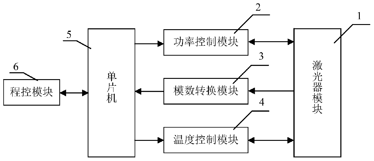
[0040] Such as figure 1 As shown, the structure includes a laser module 1, a power control module 2, an analog-to-digital conversion module 3, a temperature control module 4, a single chip microcomputer 5, a program control module 6 and a front panel 7. The power control module 2 provides the driving current to the laser module 1, the temperature control module 4 controls the operating temperature of the laser module 1 to make it work in a constant temperature state, and the analog-to-digital conversion module 3 collects the output power and the operating temperature of the laser module 1 and digitalizes the The results are sent to the single-chip microcomputer 5, the program control module is used to connect and communicate the device of the present invention with the host computer to realize the program control function, and the front panel 8 is used to operate the pump source device of the present invention and connect ...

Embodiment 2

[0041] Embodiment 2 The structure of the power control module 2 of the present invention

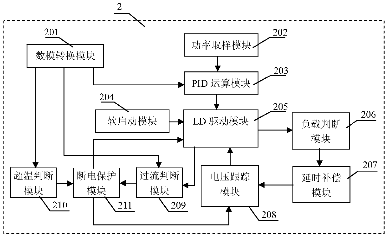
[0042] The structure of the power control module 2 is as figure 2 As shown, the structure comprising the power control module 2 includes a digital-to-analog conversion module 201, a power sampling module 202, a PID operation module 203, a soft start module 204 and an LD drive module 205, and it is characterized in that the power control module The structure of 2 also includes a load judging module 206 , a delay compensation module 207 , a voltage tracking module 208 , an overcurrent judging module 209 , an overtemperature judging module 210 and a power-off protection module 211 . The digital-to-analog conversion module 201 receives the output power parameters, current limit preset parameters, and temperature limit preset parameters sent by the microcontroller and converts them into corresponding analog signals, which are respectively output to the PID operation module 203 and the overcur...

Embodiment 3

[0046] Embodiment 3 The load judging module of the present invention

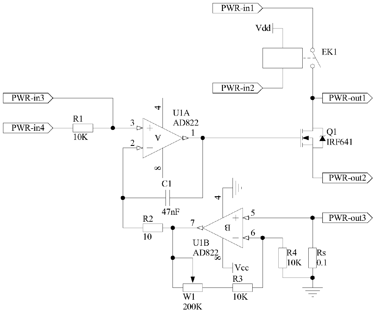
[0047] The structure of the load judging module 206 of the present invention is as follows Figure 4 As shown: the non-inverting input terminal of the operational amplifier U2A is used as the first input terminal of the load judgment module 206, which is denoted as port Vjdg-in1, and is connected to the port PWR-out1 of the LD driver module 205, and the inverting input terminal of the operational amplifier U2A is connected to the The output terminal of operational amplifier U2A is connected to one end of resistor R5, the other end of resistor R5 is connected to one end of resistor R6 and the same-inverting input terminal of operational amplifier U3A, the other end of resistor R6 is grounded, and the output terminal of operational amplifier U3A is connected to the in-phase input terminal of operational amplifier U3A. One end is connected to one end of the resistor R9, the other end of the resistor R8 is conn...


PUM


Abstract

The invention discloses a program control type high-efficiency laser pumping source module, and belongs to the technical field of electronic equipment. The module structurally comprises a laser module(1), a power control module (2), an analog-to-digital conversion module (3), a temperature control module (4), a single chip microcomputer (5), a program control module (6) and a front panel (7), wherein the main structure of the power control module (2) comprises a load judgment module (206), a time delay compensation module (207), a voltage tracking module (208), an outage protection module (211) and the like. When the module works under different output power, the module can keep the lowest electric loss, and the integral efficiency of the system is improved.

Description

technical field [0001] The invention belongs to the technical field of electronic equipment, in particular to a program-controlled high-efficiency laser pump source module. Background technique [0002] With its low threshold, high power, high beam quality, good reliability, compact structure and good heat dissipation, fiber lasers are widely used in laser fiber communication, laser space long-distance communication, industrial shipbuilding, automobile manufacturing, laser engraving, Laser marking, laser cutting, printing roll, metal and non-metal drilling / cutting / welding (brazing, quenching, cladding and deep welding), military defense security, medical equipment and other fields. A fiber laser is a laser that uses a rare earth-doped fiber as a gain medium. Fiber lasers are developed on the basis of fiber amplifiers and are composed of three basic elements: pump source, rare earth element-doped fiber, and resonant cavity. The working principle is: the photons at the pump w...

Claims


Application Information

Patent Timeline
Patent Type & Authority Patents(China)
IPC IPC(8): H01S3/102
CPCH01S3/1022
Inventor 霍佳雨唐伟莫思铭高博郭玉彬李志军邵珠峰
Owner JILIN UNIV
Why Eureka
Try Eureka