Preparation method of nitrogen doped carbon nano-array loaded iron phosphide/cobalt phosphide

A nano-array, nitrogen-doped carbon technology, applied in chemical instruments and methods, chemical/physical processes, physical/chemical process catalysts, etc., can solve the problems of high cost, slow electrochemical hydrogen production reaction kinetics, and low energy conversion efficiency. and other problems, to achieve the effect of low cost and superior hydrogen production performance

Inactive Publication Date: 2019-03-08
UNIV OF JINAN
View PDF4 Cites 11 Cited by
  • Summary
  • Abstract
  • Description
  • Claims
  • Application Information

AI Technical Summary

Problems solved by technology

However, due to the high cost, high energy consumption and low energy conversion efficiency of electrolyzed water technology, the development and application of industrial electrolyzed water are limited.
Therefore,

Method used


Image

  • Preparation method of nitrogen doped carbon nano-array loaded iron phosphide/cobalt phosphide
  • Preparation method of nitrogen doped carbon nano-array loaded iron phosphide/cobalt phosphide
  • Preparation method of nitrogen doped carbon nano-array loaded iron phosphide/cobalt phosphide

Examples


Embodiment 1

[0030] Example 1 CoP 3 / Preparation of FeP@N-C

[0031] 1.1 Preparation of carbon paper

[0032] Prepare 40mL of 1mol / L nitric acid solution in a small beaker, place the small beaker containing the nitric acid solution on a magnetic stirrer for heating in a water bath, cook the carbon paper with acid at 90°C for 1 hour at a medium speed; take out the boiled carbon Paper, mark on carbon paper, take a 50mL small beaker and clean it, and add an appropriate amount of ultrapure water to it, add the marked carbon paper to it, perform ultrasonic cleaning for 10 minutes, and then replace the ultrapure water with ethanol ultrasonic Wash for 5 minutes; then dry in the oven for 12 hours.

[0033] 1.2 Preparation of polyaniline nanoarrays (N-CNAs)

[0034] Take 50mL of ultrapure water into the beaker, place the beaker on a magnetic stirrer and start stirring, take 4.310mL of perchloric acid into the beaker with a pipette gun, then take 0.460mL of aniline solution into the previous bea...

Embodiment 2

[0039] Example 2 CoP 3 / Physicochemical properties of FeP@N-C

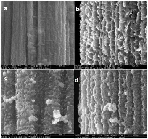
[0040] Intermediate product and final product are observed with scanning electron microscope in each preparation process in embodiment 1, and photo is as follows figure 1 As shown, among them, a is the scanning electron micrograph of carbon paper; b is the scanning electron micrograph of N-CNAs; c is the scanning electron micrograph of PANI-Fe / Co MOF; d is the CoP 3 / FeP@N-C scanning electron microscope image. Comparing Figure a and Figure b, it can be clearly seen that polyaniline grew on the original smooth carbon paper surface during the electrodeposition process, forming a highly consistent nano-array structure. After the cobalt ferrite MOF is grown, it can be seen that the N-CNAs are coated with a layer of cobalt ferrite MOF. At this time, the array is still highly ordered and the morphology is relatively complete. After low-temperature calcination and phosphating, the morphology of the array shrunk compa...

Embodiment 3

[0041] Example 3 CoP 3 Catalytic activity of / FeP@N-C

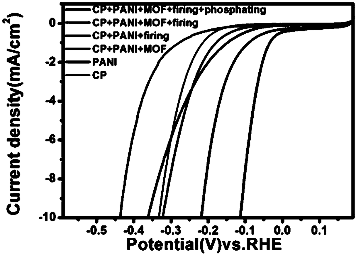
[0042] Both the intermediate product and the final product prepared in Example 1 were placed in 0.5mol / L sulfuric acid, and tested by Shanghai Chenhua Electrochemical Workstation, the potential window was 0~-0.4V, image 3 It is the linear voltammetry scanning curve of each intermediate product and the final product of Example 1, wherein, the materials and processing methods intersecting with the abscissa from left to right are CP+PANI+MOF+firing, PANI, CP, CP+PANI+ MOF, CP+PANI+firing, CP+PANI+MOF+firing+phosphating; CP stands for carbon paper, PANI stands for polyaniline nanoarray, MOF stands for Fe / Co MOF, firing stands for calcination, and phosphating stands for phosphating. By comparison, the CoP 3 The combination of / FeP@N-C has better performance than other materials (carbon paper, N-CNAs, PANI-Fe / Co MOF, etc.), and its initial overpotential is about 50mv and the catalyst surface is built at about 0.11V Current ...


PUM


Abstract

The invention provides a preparation method of nitrogen doped carbon nano-array loaded iron phosphide/cobalt phosphide. The method includes the steps: calcining polyaniline-iron cobalt metal organic framework in protective gas to obtain a precursor; performing phosphorization on the precursor in the protective gas under the heating condition to obtain the nitrogen doped carbon nano-array loaded iron phosphide/cobalt phosphide. A catalyst prepared by the method for loading a prepared novel phosphide on a nitrogen doped carbon nano-array is excellent in hydrogen producing performance, a materialmanufacturing process is easily controlled, long-time stability is good, low is lower as compared with an existing noble metal catalyst, and the catalyst can be applied to production of electrochemical cell hydrogen evolution electrodes.

Description

technical field [0001] The invention belongs to the field of preparation of novel catalytic materials, and in particular relates to a preparation method of an iron-based phosphide electrode material. Background technique [0002] Since the 19th century, traditional fossil energy sources such as coal, oil, and natural gas have supported the rapid development of social economy and the progress of human civilization. However, the traditional fossil energy has a great impact on the environment when it is burned. At the same time, as a non-renewable energy source, the extremely fast consumption rate makes the fossil energy gradually exhausted. With the continuous development of human society, it is imperative to develop a safe, efficient and sustainable clean energy. As a clean, non-polluting secondary energy source, hydrogen has a high mass energy density, and is considered by many to be an ideal solution to energy problems. Among many hydrogen production methods, electrolysis...

Claims


Application Information

Patent Timeline
IPC IPC(8): B01J27/24C25B1/04C25B11/06
CPCB01J27/24B01J35/0033C25B1/04C25B11/091Y02E60/36
Inventor 赵振路蒋彤侯树平王建荣
Owner UNIV OF JINAN
Why Eureka
Try Eureka