Urban organic solid waste coupling dry pyrolysis gasification system

A technology of organic solid waste, pyrolysis and gasification, which is used in pyrolysis treatment of sludge, gas dust removal, combined devices, etc. Chain length and other problems, to achieve the effect of strong process controllability and operability, reducing exhaust gas treatment costs and reducing heat conversion links

Pending Publication Date: 2019-03-29
HUBEI JIADE TECH
View PDF1 Cites 3 Cited by
  • Summary
  • Abstract
  • Description
  • Claims
  • Application Information

AI Technical Summary

Problems solved by technology

[0005] At present, conventional equipment such as externally heated rotary furnaces and fixed beds are mostly used for pyrolysis and gasification of organic solid waste such as sludge, which do not match the characteristics of high ash content and low ash melting point of dewatered sludge, and the gasification yield is low (< 50%) gasification is not complete
AG's Balingen sludge gasification project in Germany and Japan's Tokyo Metropolitan Sewerage Bureau have developed a system that utilizes dry sludge gasification to generate gas for power generation. Both use steam pre-drying. The system is complex, the energy conversion chain is long, and the heat loss is large, which has not been realized. True coupling of drying and pyrolysis gasification

Method used


Image

  • Urban organic solid waste coupling dry pyrolysis gasification system
  • Urban organic solid waste coupling dry pyrolysis gasification system
  • Urban organic solid waste coupling dry pyrolysis gasification system

Examples


specific example

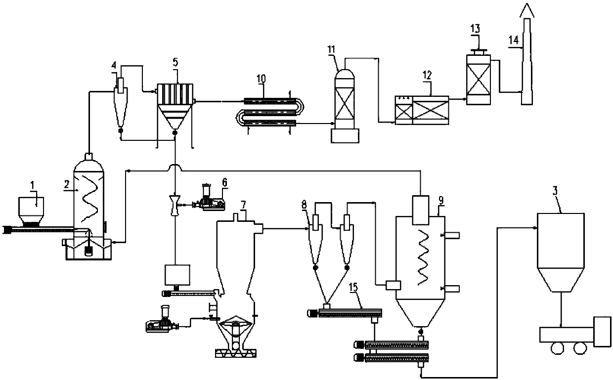
[0047] The dewatered sludge (water content 80%) of a sewage plant is 120 tons / day, and the dry sludge conveying screw pump is used to send it to the sludge feeding storage device, and then enters the pre-drying device for drying, reducing the water content to 20-30 %, the reduction is 30-34.3 tons. After drying, the sludge is sent to the cyclone fluidized bed gasification furnace through the Roots blower pneumatic conveying equipment. The pyrolysis reaction temperature is 600-800°C. After the pyrolysis reaction, 11.0-13.0 tons of ash and pyrolysis gas are produced. After being cooled to 100°C by the cold slag conveyor, it is densely transported into the ash slag bin by the warehouse pump, and then transported to the brick factory to manufacture pavement bricks and other products for final disposal and resource utilization. The combustible gas is separated from the ash by the high-temperature separator The slag is sent to the second combustion chamber to generate high-temperatu...


PUM


Abstract

The invention relates to an urban organic solid waste coupling dry pyrolysis gasification system, which comprises a sludge feeding storage device, a pre-drying device, a cyclone separator, a sludge special cloth bag and a smoke gas afterheat recovery device in sequential connection, wherein the cyclone separator and a sludge outlet of the special sludge cloth bag are connected with a cyclone fluidized bed gasification furnace; the cyclone fluidized bed gasification furnace is connected with a high-temperature separator; the high-temperature separator is connected with a second combustion chamber; high-temperature smoke gas generated by the second combustion chamber is used as a heat source of the pre-drying device; ash slag generated by the high-temperature separator and the second combustion chamber is fed into an ash slag cabin after being cooled by a cold slag conveying machine. Through the integration and the optimization by the system, a pre-drying and pyrolysis gasification two-section process is used; the process controllability and the operability are high. Compared with a conventional fixed bed or steam drying and fluidized bed gasification combination process, the processhas the advantages that the heat efficiency is improved by 10 to 15 percent. The sludge is subjected to pyrolysis gasification, so that the exhaust of harmful substances and NOx and Sox can be greatly reduced through being compared with the exhaust value of direct combustion; the tail gas treatment cost is reduced.

Description

technical field [0001] The invention relates to the field of ecological environmental protection, and more specifically relates to a coupled drying pyrolysis gasification system for urban organic solid waste. Background technique [0002] It is predicted that the sludge output of urban sewage plants will reach more than 80 million tons in 2020. Sludge has a high water content, is perishable and has a strong odor, and contains a large number of pathogenic bacteria, parasite eggs, heavy metals such as chromium and mercury, and toxic, harmful and carcinogenic substances that are difficult to degrade, such as dioxin. How to treat sludge in a harmless and resourceful way is a major environmental protection issue. [0003] Solving the sludge problem should be "disposal-based treatment". The sludge disposal methods mainly include sanitary landfill, land use, production of building materials, and incineration. The application of sanitary landfill is decreasing due to problems such...

Claims


Application Information

Patent Timeline
IPC IPC(8): C10B53/00C10B57/10C10B57/00B01D50/00C10K1/02
CPCC10B53/00C10B57/00C10B57/10C10K1/02C10K1/024C10K1/026B01D50/20C02F11/10C02F11/13C02F11/16
Inventor 余桥谭明照袁鹏飞周桃红张立民马彩凤张雷泽雨
Owner HUBEI JIADE TECH
Why Eureka
Try Eureka