Light-driving floating and diving motion device based on bubbles

A motion device and optical drive technology, applied in transportation and packaging, motor vehicles, machines/engines, etc., can solve the problems of limited practical application, difficult motion control, unsustainable, etc., and achieve the goal of improving light-to-heat conversion efficiency and wide application value Effect

Active Publication Date: 2019-04-12
SHANGHAI JIAO TONG UNIV
View PDF3 Cites 4 Cited by
  • Summary
  • Abstract
  • Description
  • Claims
  • Application Information

AI Technical Summary

Problems solved by technology

Using an exercise process that releases gas based on a chemical reaction is not sustainable
In addition, driven by chemical reactions, it is

Method used


Image

  • Light-driving floating and diving motion device based on bubbles
  • Light-driving floating and diving motion device based on bubbles
  • Light-driving floating and diving motion device based on bubbles

Examples


Example Embodiment

[0038] Example 1

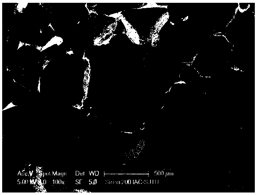
[0039] (1) Mix sodium chloride particles, carbon black particles and liquid PDMS (the three can be mixed according to actual needs, and the general mass ratio is 606:1:100), then pour them into the mold and put it in the oven to make it solidification. Then it is soaked in water, and through continuous extrusion, the sodium chloride particles inside the PDMS are continuously dissolved in the water, leaving small holes of the same size in the corresponding parts. After the sodium chloride particles are completely dissolved, they are dried in an oven to obtain porous PDMS. For its surface structure, see figure 2 As shown, it can be seen that the surface has numerous micro-nano-sized holes.

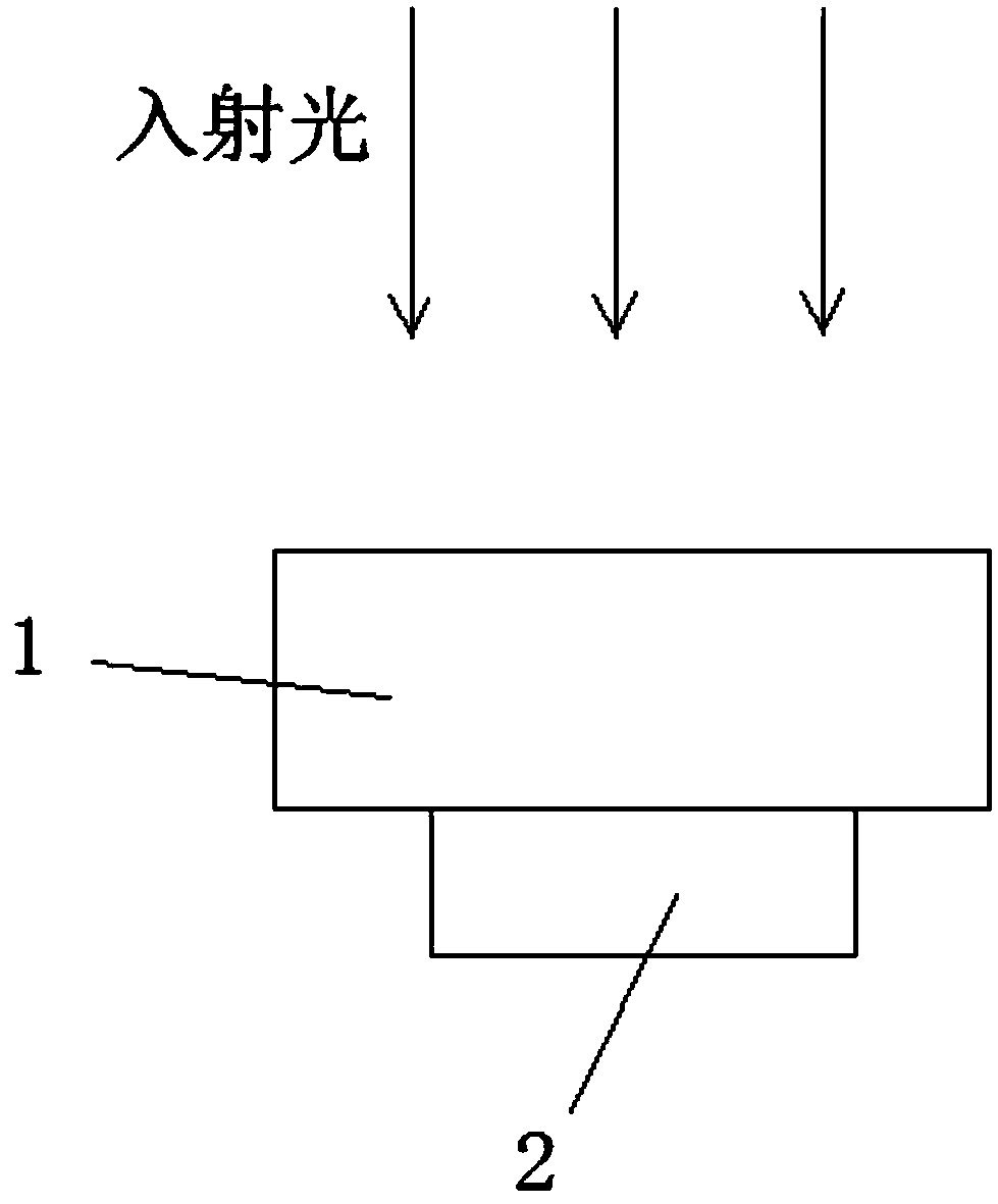
[0040] (2) Cut the porous PDMS to a suitable size. Through measurement and calculation, iron blocks are used as the weight to make the density slightly greater than that of water, to the extent that it can just dive into the water.

[0041] (3) Put the porous PDMS with iron a...

Example Embodiment

[0043] Example 2

[0044] In this embodiment, the material with electromagnetic wave absorption properties is nano-gold particles; using the method in the embodiment, sodium chloride particles and PDMS are used to make porous PDMS. Then immerse it in 0.5% (m / v) chloroauric acid ethanol solution or drip 0.5% (m / v) chloroauric acid ethanol solution on the porous PDMS, because the residual curing agent in PDMS will cause chlorine Gold acid is reduced, so gold nanoparticles can be synthesized inside the porous PDMS after standing at room temperature for a period of time. Use 532nm laser as the light source driver movement. The rest is the same as in Example 1.

Example Embodiment

[0045] Example 3

[0046] Use metal foam directly as the base material. Put the copper foam at 0.065M K 2 S 2 O 8 In a mixed solution of 2.5M KOH and heated at 60°C for 30 minutes, a chemical reaction occurs on the surface to form a certain microstructure. Then graphene is bonded to the surface of the copper foam through organic matter as an electromagnetic wave absorbing material. Then immerse the whole body in 1.0% (wt%) 1H, 1H, 2H, 2H-perfluorodecyltriethoxysilane (PFTS) ethanol solution, react at room temperature for 30 minutes, then take out the solution and put it at 80℃ After heating for 30 minutes, the surface of the copper foam exhibits hydrophobicity through the above chemical modification. The rest is the same as in Example 1.


PUM


Abstract

The invention relates to a light-driving floating and diving motion device based on bubbles. The device comprises a floating and diving motion main body, wherein the floating and diving motion main body is formed by compounding a photo-thermal conversion material with a high-efficiency electromagnetic wave absorption characteristic and a base material, wherein a micro-nano structure capable of constraining a layer of the micro-bubbles is further processed on the surface of the photo-thermal conversion material of the floating and diving motion main body. Compared with the prior art, accordingto the device, driving by the thermal bubbles based on the photo-thermal effect is achieved; light energy is converted into kinetic energy of the device, so that the controllable motion under the light condition is realized; the design of a motion body in a liquid is simplified, and a novel method for driving an object in the liquid is developed; and the device can move in various liquids such aswater and other organic liquids, so that the device has a wide application prospect.

Description

Technical field [0001] The invention belongs to the technical field of new type driving of functional materials, and relates to a bubble-based optical drive snorkeling motion device. Background technique [0002] The study of driving methods in liquids has broad application prospects, which can be used to promote the movement of objects in liquids; combined with photocatalytic substances such as titanium dioxide, etc., used to degrade pollutants in water and purify water sources. The existing driving methods for snorkeling are mainly driven by gas released by chemical reactions. However, during exercise, the chemicals required for chemical reactions such as hydrogen peroxide, magnesium, calcium carbonate, etc. will gradually be consumed as the exercise progresses. The use of motion processes based on the reaction of chemical substances to release gases is not sustainable. In addition, driven by chemical reactions, it is difficult to exercise effective control during exercise. ...

Claims


Application Information

Patent Timeline
IPC IPC(8): F03G7/00B63B38/00
CPCB63B35/00F03G7/005
Inventor 孟凡臣宋成轶栾添郝伟刘颜铭冯睿尚文陶鹏邓涛
Owner SHANGHAI JIAO TONG UNIV
Why Eureka
Try Eureka