Method of plasma decomposing hydrogen sulfide

A technology of plasma and hydrogen sulfide, applied in the field of plasma chemistry, can solve the problems of low conversion rate of hydrogen sulfide and high energy consumption of decomposition

Active Publication Date: 2021-09-14
CHINA PETROLEUM & CHEM CORP +1
View PDF12 Cites 0 Cited by
  • Summary
  • Abstract
  • Description
  • Claims
  • Application Information

AI Technical Summary

Problems solved by technology

[0017] The purpose of the present invention is to provide a new method for plasma decomposing hydrogen sulfide in order to overcome the defects of low conversion rate of hydrogen sulfide and high decomposition energy consumption in the hydrogen sulfide decomposition reaction existing in the prior art

Method used


Image

  • Method of plasma decomposing hydrogen sulfide
  • Method of plasma decomposing hydrogen sulfide
  • Method of plasma decomposing hydrogen sulfide

Examples


specific Embodiment approach

[0088] Nitrogen gas was introduced into the inner barrel of the plasma reactor from the reactor inlet to purge air in the discharge area, and the gas was drawn from the product outlet. At the same time, the heat-conducting medium is introduced into the outer cylinder from the heat-conducting medium inlet, and the introduced heat-conducting medium is led out from the heat-conducting medium outlet. The temperature of the heat transfer medium is maintained at the temperature required for the system reaction. Then feed the raw material gas containing hydrogen sulfide into the inner cylinder of the plasma reactor from the inlet of the reactor, and the raw material gas fills each reaction tube. After the gas flow of the raw material is stable, turn on the high-voltage power supply, and adjust the voltage and frequency to make the central high-voltage electrode and the A plasma discharge field is formed between the ground electrodes. The hydrogen sulfide gas is ionized in the discha...

Embodiment 1

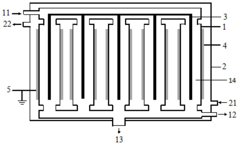
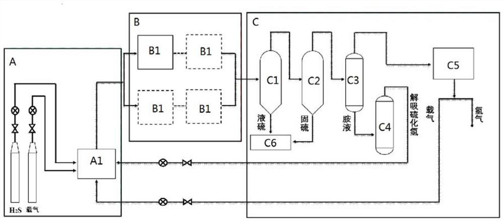
[0137] using the image 3 The plasma system for decomposing hydrogen sulfide in the shown flow chart performs the method of the present invention for decomposing hydrogen sulfide by plasma, and the plasma reactor in this embodiment has figure 1 shown structure.

[0138] The process flow of this embodiment is shown in the foregoing specific embodiment, and the structural parameters of the plasma reactor are as follows:

[0139] Plasma reactors include:

[0140] The inner cylinder is provided with a reactor inlet, a gas product outlet and a liquid product outlet respectively, and the inner cylinder contains 4 reaction tubes arranged in parallel, and the top and bottom of each of the reaction tubes are correspondingly connected. , so that the raw materials entered from the reactor inlet can enter into each of the reaction tubes respectively, and the gaseous products produced in each of the reaction tubes can be drawn out from the gas product outlet, and each of the reaction tub...

Embodiment 2

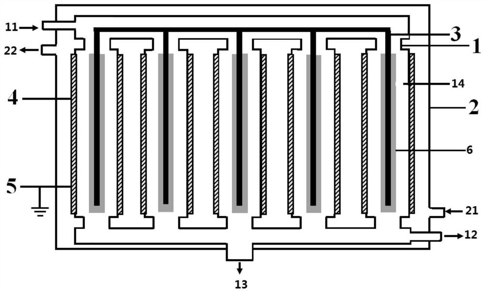
[0152] using the image 3 The plasma system for decomposing hydrogen sulfide in the shown flow chart performs the method of the present invention for decomposing hydrogen sulfide by plasma, and the plasma reactor in this embodiment has figure 2 shown structure.

[0153] The process flow of this embodiment is shown in the foregoing specific embodiment, and the structural parameters of the plasma reactor are as follows:

[0154] Plasma reactors include:

[0155] The inner cylinder is provided with a reactor inlet, a gas product outlet and a liquid product outlet respectively, and the inner cylinder contains 4 reaction tubes arranged in parallel, and the top and bottom of each of the reaction tubes are correspondingly communicated, respectively, The raw materials entering from the inlet of the reactor can enter into each of the reaction tubes respectively, and the gaseous products produced in each of the reaction tubes can be drawn out from the gas product outlet, and the gase...


PUM


Abstract

The invention relates to the field of plasma chemistry, and discloses a method for decomposing hydrogen sulfide by plasma, comprising: introducing raw material gas containing hydrogen sulfide into a plasma system containing a plasma reactor for sulfurization under dielectric barrier discharge conditions Hydrogen decomposition reaction, the dielectric barrier discharge conditions include: a discharge voltage of 5-30kV, a discharge frequency of 200-30000Hz; and the conditions of the hydrogen sulfide decomposition reaction include: a reaction temperature of 0-800°C, a reaction pressure of -0.06 MPa to 0.6MPa, the residence time of the reactant in the plasma reactor is 1×10 ‑5 ~120s. The method for decomposing hydrogen sulfide by plasma provided by the present invention can obtain a higher conversion rate of hydrogen sulfide under dielectric barrier discharge conditions by adopting specific discharge conditions and hydrogen sulfide decomposition reaction conditions.

Description

technical field [0001] The invention relates to the field of plasma chemistry, in particular to a method for decomposing hydrogen sulfide by plasma. Background technique [0002] hydrogen sulfide (H 2 S) is a highly toxic and foul-smelling acid gas, which not only causes corrosion of metals and other materials, but also easily leads to poisoning and deactivation of catalysts in chemical production; in addition, hydrogen sulfide can also harm human health and cause environmental pollution. Therefore, the harmless treatment of a large amount of hydrogen sulfide gas generated in industrial fields such as petroleum, natural gas, coal and mineral processing needs to be solved in terms of process requirements, equipment maintenance and environmental protection requirements. [0003] At present, the Claus process is commonly used in industry to treat hydrogen sulfide, and the method is to partially oxidize hydrogen sulfide to obtain sulfur and water. Although this method solves t...

Claims


Application Information

Patent Timeline
Patent Type & Authority Patents(China)
IPC IPC(8): C01B17/04C01B3/04
CPCC01B3/04C01B17/0495Y02E60/36
Inventor 张婧徐伟张铁任君朋朱云峰石宁孙峰
Owner CHINA PETROLEUM & CHEM CORP
Why Eureka
Try Eureka