Laser remelting method for plasma cathode electrolytic deposition ceramic coating surface

A plasma and ceramic coating technology, which is applied in surface reaction electrolytic coating, electrolytic coating, electrolytic inorganic material coating, etc. problems, to achieve the effect of improving structural compactness, increasing surface hardness, and reducing porosity

Active Publication Date: 2020-02-11
NORTHWESTERN POLYTECHNICAL UNIV
View PDF5 Cites 2 Cited by
  • Summary
  • Abstract
  • Description
  • Claims
  • Application Information

AI Technical Summary

Problems solved by technology

[0003] At present, the limitations of plasma cathodic electrodeposition technology are mainly manifested in the fact that the structure of the ceramic coating is not dense enough, relatively loose and porous, especially when the coating thickness is high, the surface is prone to a small amount of cracking and peeling, which will cause the coating The decrease of layer surface hardness and the decrease of wear resistance

Method used


Image

  • Laser remelting method for plasma cathode electrolytic deposition ceramic coating surface
  • Laser remelting method for plasma cathode electrolytic deposition ceramic coating surface
  • Laser remelting method for plasma cathode electrolytic deposition ceramic coating surface

Examples


Embodiment 1

[0048] Titanium-aluminum alloy is selected as the base material and processed according to the following steps:

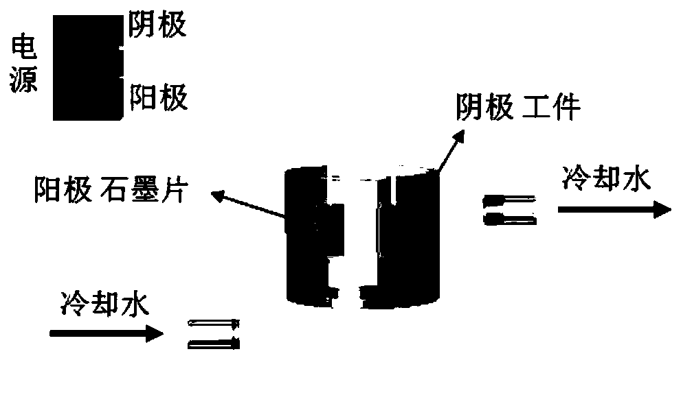
[0049] 1. Pretreatment of the substrate material: choose 50# sandpaper-400# sandpaper to polish the alloy substrate, remove the oil stain and rust layer on the surface of the substrate, rinse the polished substrate material with deionized water, and use acetone or absolute ethanol Ultrasonic cleaning for 3min–5min, then rinse with deionized water, and air dry naturally. The alloy matrix sample is used as the anode, and the stainless steel sheet is used as the cathode. The plasma power supply is used for micro-arc oxidation treatment, and the plasma micro-arc oxidation power supply is used for micro-arc oxidation treatment. The working fluid composition is: Na 2 SiO 3 3g / L–30g / L, NaAlO 2 2g / L–20g / L, Na 3 PO 4 2g / L–30g / L, NaOH 1g / L–5g / L, the process parameters are: frequency 500Hz, duty cycle 20%, current density 5A / dm 2 , temperature 10°C, time 5min. Rinse ...

Embodiment 2

[0070] The difference between this embodiment and embodiment 1 is that the base material described in step 1 is titanium and titanium alloy, aluminum and aluminum alloy, magnesium and magnesium alloy or stainless steel.

[0071] Other implementation steps are the same as in Example 1.

Embodiment 3

[0073] The difference between this embodiment and embodiment 1 or 2 is: in the deionized water / ethanol solvent described in step 2, the volume ratio of deionized water and ethanol is 0 / 10, 1 / 9, 2 / 8, 3 / 7, 4 / 6, 6 / 4, 7 / 3, 8 / 2, 9 / 1, 10 / 0.

[0074] Other implementation steps are identical with embodiment 1 or 2.


PUM

PropertyMeasurementUnit
thicknessaaaaaaaaaa
friction coefficientaaaaaaaaaa

Abstract

The invention relates to a laser remelting method for a plasma cathode electrolytic deposition ceramic coating surface. The laser remelting method comprises the following steps of firstly, electrolytically depositing the ceramic coating on the surfaces of titanium and titanium alloy, aluminum and aluminum alloy, magnesium and magnesium alloy, titanium aluminum alloy, stainless steel and the like by using the plasma cathode, and then carrying out laser remelting modification strengthening method. In the laser remelting process, under the action of high-energy radiation of laser beam, the localarea of ceramic coating within the coverage area of the light spot will form a molten pool and melting is carried out, and the melts will undergo phase change under high-temperature condition to generate second-phase substances with higher hardness and the like; meanwhile, the molten pool can be quenched depending on the matrix material with lower temperature, the microstructure of the coating material can be refined, and the cooled ceramic coating structure can become uniform and compact. The factors are helpful to improve and enhance the structural compactness, surface hardness, binding force, high temperature oxidation resistance, wear resistance and corrosion resistance of the plasma cathode electrolytic deposition ceramic coating.

Description

technical field [0001] The invention belongs to the technical field of surface modification of metal materials, and relates to a method for laser remelting of a plasma cathodic electrolytic deposition ceramic coating surface, and relates to titanium and titanium alloys, aluminum and aluminum alloys, magnesium and magnesium alloys, and titanium-aluminum alloys Laser remelting modification and strengthening method of plasma cathodic electrolytic deposition of ceramic coatings on surfaces such as stainless steel and stainless steel to improve the structural compactness, bonding force, surface hardness and wear resistance of ceramic coatings. Background technique [0002] Plasma cathodic electrolytic deposition technology can be used to prepare in-situ grown ceramic coatings on the surfaces of titanium and titanium alloys, aluminum and aluminum alloys, magnesium and magnesium alloys, titanium aluminum alloys, and stainless steel. The composition of the ceramic coating has nothin...

Claims


Application Information

Patent Timeline
Patent Type & Authority Applications(China)
IPC IPC(8): C25D11/02C25D9/08C25D5/48
CPCC25D11/026C25D9/08C25D5/48
Inventor 吴向清谢发勤王少青董美娟
Owner NORTHWESTERN POLYTECHNICAL UNIV
Why Eureka
Try Eureka