Method for laser composite chemical polishing of titanium alloy based on galvanometer
A chemical polishing and titanium alloy technology, which is applied in the field of precision surface treatment, can solve the problems of inability to achieve precise polishing of selected areas, inability to use for a long time, corrosion of electrolytic devices, etc., to achieve the elimination of airtight devices, easy configuration, and recycling high rate effect
- Summary
- Abstract
- Description
- Claims
- Application Information
AI Technical Summary
Problems solved by technology
Method used
Image
Examples
Embodiment 1
[0027] (1) Sample pretreatment: The titanium alloy is processed into a sample of 40mm×20mm×4mm by wire cutting, and the surface is cleaned with a milling cutter.
[0028] (2) Test the surface roughness S of the sample with a three-dimensional profiler a = 1.32um.
[0029] (3) Preparation of chemical solution: Add 12.5g of sodium nitrate, 4.95g of potassium chloride and 4.97g of calcium chloride into 1000ml of deionized water, stir until fully dissolved to obtain a chemical solution. Heat to 37°C and keep warm.
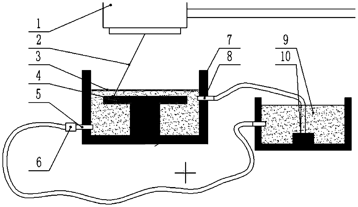
[0030] (4) Laser polishing treatment and process parameter setting: place the sample whose roughness has been measured in the chemical solution in step (3), immerse the sample, and keep the sample 2mm away from the surface of the solution. Set the water inflow and outflow to 100ml / min, place it on a 500w galvanometer laser workbench, set the laser power to 300w; scan speed to 400mm / s, line spacing to 0.02mm, spot size to 10mm, defocus amount is +2mm. The number of ...
Embodiment 2
[0033] (1) Sample pretreatment, measure the initial roughness S a =1.31um, the solution preparation steps refer to Example 1, laser polishing treatment and process parameter setting: place the sample whose roughness has been measured in the chemical solution of step (3), immerse the sample, and the sample is 2mm away from the solution surface. Set the water inflow and outflow to 100ml / min, place it on a 500w galvanometer laser workbench, set the laser power to 400w; scan speed to 600mm / s, line spacing to 0.04mm, spot size to 12mm, defocus is +4mm. The number of scans is one time, and the scanning area is 10mm×10mm.
[0034] (2) Take out the polished sample, wash it with absolute ethanol, and dry it. The roughness S measured under the three-dimensional profile a = 0.45um.
Embodiment 3
[0036] (1) Sample pretreatment, measure the initial roughness S a =1.32um, the solution preparation steps refer to Example 1, laser polishing treatment and process parameter setting: place the sample whose roughness has been measured in the chemical solution of step (3), immerse the sample, and the sample is 2mm away from the solution surface. Set the water inflow and outflow to 100ml / min, place it on a 500w galvanometer laser workbench, set the laser power to 500w; scan speed to 800mm / s, line spacing to 0.06mm, spot size to 15mm, defocus is +6mm. The number of scans is one time, and the scanning area is 10mm×10mm.
[0037] (2) Take out the polished sample, wash it with absolute ethanol, and dry it. The roughness S measured under the three-dimensional profile a = 0.48um.
PUM
| Property | Measurement | Unit |
|---|---|---|
| Roughness | aaaaa | aaaaa |
| Roughness | aaaaa | aaaaa |
| Roughness | aaaaa | aaaaa |
Abstract
Description
Claims
Application Information
 - R&D
- Intellectual Property
- Life Sciences
- Materials
- Tech Scout
- Unparalleled Data Quality
- Higher Quality Content
- 60% Fewer Hallucinations
Browse by: Latest US Patents, China's latest patents, Technical Efficacy Thesaurus, Application Domain, Technology Topic, Popular Technical Reports.
© 2025 PatSnap. All rights reserved.Legal|Privacy policy|Modern Slavery Act Transparency Statement|Sitemap|About US| Contact US: help@patsnap.com

