
The gas generator

A technology for gas generators and shells, which is applied to the generation of compressed gas, explosives, pedestrian/passenger safety arrangements, etc. It can solve the problems of filter power loss, large size and weight of gas generators, and failure of gas generators. Achieve the effects of avoiding impact and failure, reducing molten copper residue, and reducing output slope

Active Publication Date: 2021-09-03
HUBEI HANGPENG CHEM POWER TECH
View PDF14 Cites 0 Cited by
  • Summary
  • Abstract
  • Description
  • Claims
  • Application Information

AI Technical Summary

Problems solved by technology

[0012] This kind of pyrotechnic gas generator with a cup-shaped lower shell, because the gas flow has the flow characteristic of tending to the exhaust port, the filter screen of the traditional structure gas generator is approximately equal to the height of the generator, and the exhaust hole design of the traditional structure generator On the upper casing, due to the above-mentioned characteristics of gas fluidity, only the filter part highly overlapped with the upper casing plays the role of filtering the residue generated by the combustion of the gas-generating chemical, so the filter loses part of the power, which is not conducive to the small size of the gas generator lightweight
[0013] Because the utilization rate of the filter is not high, if the gas purity is improved, the weight of the filter needs to be increased, resulting in a large and heavy size and weight of the entire gas generator
In addition, the gas-generating chamber of the existing pyrotechnic gas generator is filled with cylindrical gas-generating medicines. When the ignition powder acts on the gas-generating medicines, all the gas-generating medicines are ignited at one time, and the gas-generating medicines burn without stages, resulting in pyrotechnic The initial slope output of the pyrotechnic gas generator is too high, and the initial slope is too high, which has a great impact on the pyrotechnic gas generator, which may easily cause the gas generator to fail

Method used


Image

  • The gas generator
  • The gas generator
  • The gas generator

Examples


preparation example Construction

[0091] The preparation method of the gas generant composition of the present invention can be prepared by wet granulation, spray granulation or dry granulation. Among them, spray granulation or dry granulation can adopt the traditional granulation process.

[0092] Wherein the specific preparation method of wet granulation comprises the following steps:

[0093] (1) Mix guanidine nitrate, basic copper nitrate, strontium nitrate, ammonium perchlorate and slagging agent to obtain the first material; mix in the mixing equipment, mixing time ≥ 5min; the mixing equipment can be V-type mixing machine, three-dimensional multi-directional motion mixer, automatic lifting hopper mixer, vibrating mill, ribbon mixer or acoustic resonance mixer.

[0094] (2) Add water to the first material and carry out wet mixing to obtain the second material. The wet mixing time is 20min to 60min; the amount of water added is 8% to 15% of the total mass of the first material; distilled water is preferab...

Embodiment 1

[0120] The gas generant composition comprises the following components in mass percent:

[0121] Guanidine Nitrate 40%

[0122] Basic copper nitrate 42.75%

[0123] Strontium nitrate 8%

[0124] Ammonium perchlorate 3%

[0125] Barium zirconate 5.5%

[0126] Talc 0.75%

[0127] After these components are weighed, they are compressed into discs with a diameter of 5 mm and a thickness of 1.9 mm by wet granulation and rotary tablet press. The specific preparation method is: guanidine nitrate, basic copper nitrate, strontium nitrate, ammonium perchlorate Mix the first material with barium zirconate through a mixing device; add 15% distilled water to the first material and carry out wet kneading for 60 minutes to obtain the second material, and pass the second material through a 40-mesh screen to obtain the third material; The third material is dried until the water content is less than 0.5% of the total mass of the third material, and the fourth material is obtained through a...

Embodiment 2

[0144] The gas generant composition comprises the following components in mass percent:

[0145] Guanidine Nitrate 50%

[0146] Basic copper nitrate 41.5%

[0147] Strontium nitrate 1.5%

[0148] Ammonium perchlorate 2%

[0149] Strontium Zirconate 4%

[0150] Talc 1%

[0151] After these components are weighed, they are compressed into discs with a diameter of 5 mm and a thickness of 1.9 mm by wet granulation and rotary tablet press. The specific preparation method is: guanidine nitrate, basic copper nitrate, strontium nitrate, ammonium perchlorate Mix with strontium zirconate and talcum powder to obtain the first material; add 10% distilled water to the first material and carry out wet kneading for 50 minutes to obtain the second material, and pass the second material through a 35-mesh screen to obtain the third material ; The third material is dried until the water content is less than 0.5% of the total mass of the third material, and the fourth material is obtained by...


PUM

PropertyMeasurementUnit
thicknessaaaaaaaaaa
thicknessaaaaaaaaaa
tensile strengthaaaaaaaaaa

Abstract

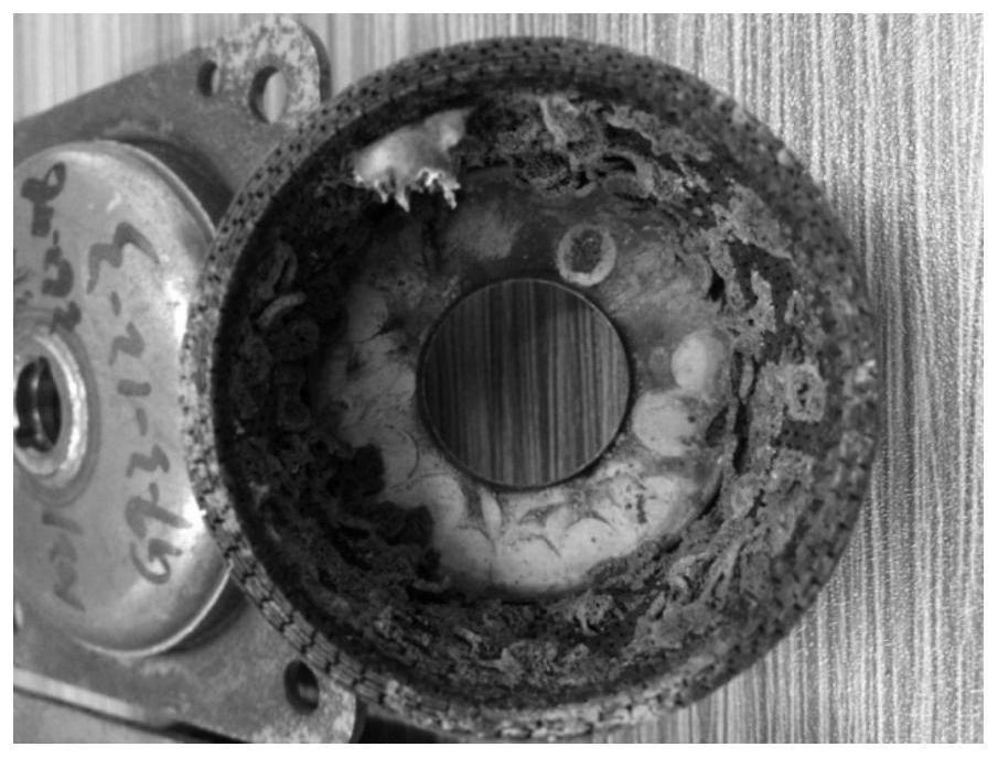
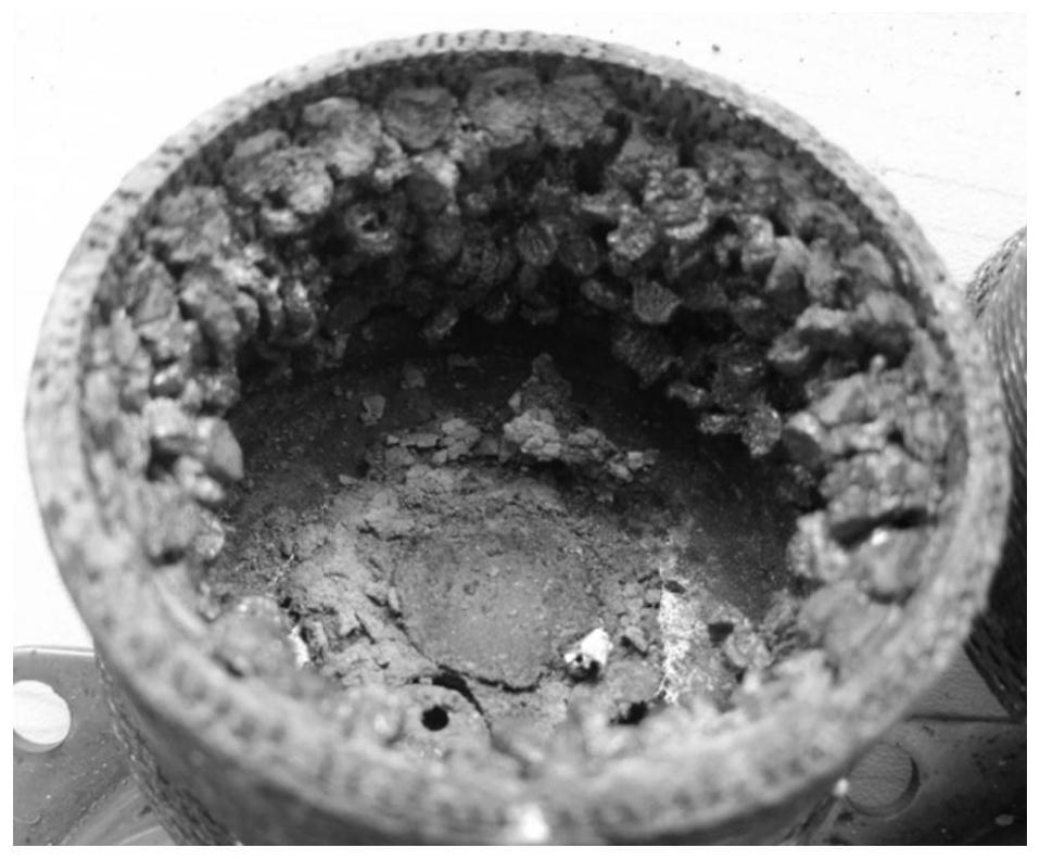
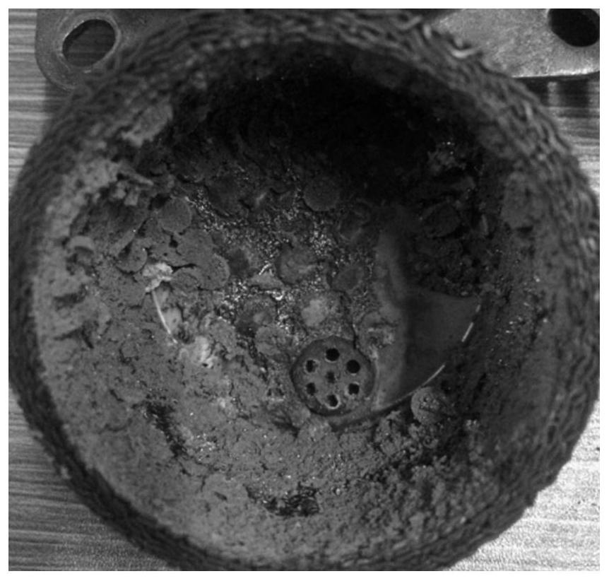
The invention relates to providing a gas generator, which realizes staged combustion by changing the structure and layout of the filter and the formula and drug type of the gas-generating medicine, thereby improving the filtration efficiency of the filter, reducing the initial output slope of the gas generator, and realizing The gas generator is small in size, light in weight, and reliable in operation; in addition, through the design of the composition formula of the gas generating agent, zirconate, silicate or a mixture of zirconate and silicate is used as the slagging agent, and the other The combination of components enables the tablets to condense and gather in the filter screen after burning, and maintains the shape before burning very well, completely avoiding the melting and splashing of the tablets after burning and burning the air pockets, so that the slag formation during the burning of the gas generant composition is improved. At least 50%.

Description

technical field [0001] The invention relates to a gas generator, which belongs to the technical field of automobile safety airbag gas generators. Background technique [0002] Automobile airbag gas generating agent is loaded into the gas generator as a gas generating agent, and is triggered when needed to generate a large amount of gas. The airbag consists of a gas generator and an air bag. Generally, when the collision exceeds the preset intensity, the gas generator is activated and triggered, and starts to burn the gas generating agent inside to generate gas, inflate the air bag, and form a cushion air cushion between the interior and the human body to protect the human body from injury. [0003] The gas generating agent in the early stage is mainly a gas generating agent formula of sodium azide type. This formula has many advantages such as stable combustion, low combustion temperature, easy ignition, low internal pressure, high gas production rate, and less residue. Ho...

Claims


Application Information

Patent Timeline
Patent Type & Authority Patents(China)
IPC IPC(8): C06D5/06C06B29/22C06B21/00C06B23/00B60R21/264
CPCB60R21/2644C06B21/0066C06B23/009C06B29/22C06D5/06
Inventor 罗运强杜涛张俊任响宁沈晓琛
Owner HUBEI HANGPENG CHEM POWER TECH
Learn More