Adaptive optical aberration correction system and method in STED super-resolution technology

A technology of adaptive optics and super-resolution technology, which is applied in the field of adaptive optics aberration correction system, can solve the problems of increasing system cost and complexity, and achieve the effects of rapid simultaneous imaging quality optimization, improvement of focus quality, and cost reduction

Active Publication Date: 2021-03-19
ZHEJIANG UNIV
View PDF0 Cites 0 Cited by
  • Summary
  • Abstract
  • Description
  • Claims
  • Application Information

AI Technical Summary

Problems solved by technology

However, due to the differences in the shape and optical path of the excitation beam and the depletion beam in the STED super-resolution system, it is difficult to use a single deformable mirror or a spatial light modulator to perform phase compensation and spot recovery on the two beams at the same time, which greatly increases the system cost. cost and complexity, the present invention designs an adaptive optical aberration correction system, using a single spatial light modulator to synchronously correct the aberrations of the excitation beam and the loss beam in different regions, which can greatly improve the performance of STED super-resolution imaging in scattering tissues ability

Method used


Image

  • Adaptive optical aberration correction system and method in STED super-resolution technology
  • Adaptive optical aberration correction system and method in STED super-resolution technology
  • Adaptive optical aberration correction system and method in STED super-resolution technology

Examples


Embodiment 1

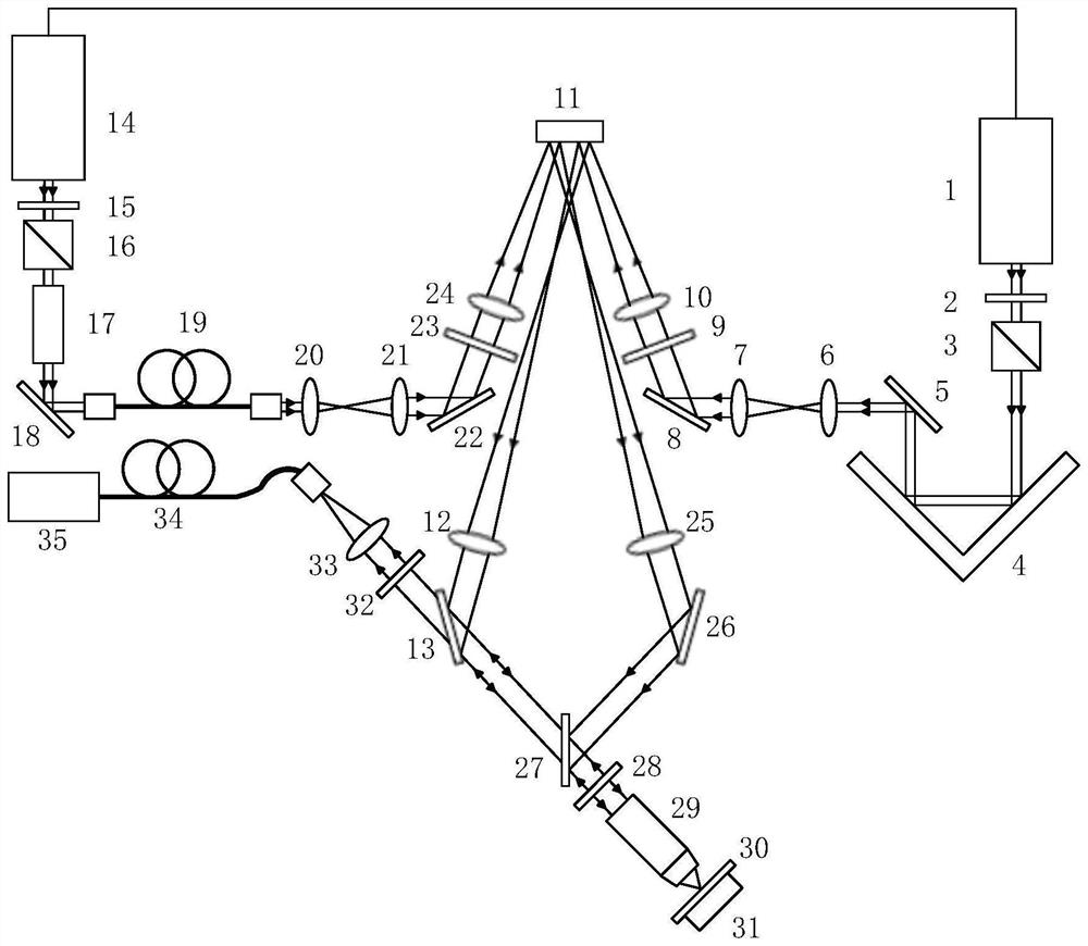
[0048] (1) Place an ordinary glass slide on the stage 31, the excitation light source 1 sends a pulsed laser beam, the excitation beam is adjusted to linearly polarized light through the first half-wave plate 2, and the power is adjusted by the first polarization beam splitter prism 3, and the excitation beam passes through After the optical delay line 4, the outgoing light from the first reflector 5 passes through the converging lens 6 of the first beam expander module and the collimating lens 7 of the first beam expander module to expand the beam, and then is reflected by the second reflector 8 and passes through the second half-wave The polarization state is adjusted by the sheet 9, and the incident beam is converged by the first converging lens 10 into the right half area of ​​the spatial light modulator 11 that is not loaded with the modulation phase. 13 reflection, and then transmitted through the second dichroic mirror 27, then adjusted to the circular polarization state...

Embodiment 2

[0060] (1) The excitation light source 1 sends a pulsed laser beam, the excitation beam is adjusted to linearly polarized light through the first half-wave plate 2, the first polarizing beam splitter prism 3 adjusts the power, and the excitation beam passes through the optical delay line 4 from the first reflection mirror 5 The outgoing light is expanded by the converging lens 6 and the collimating lens 7, and then reflected by the second reflector 8 and adjusted by the second half-wave plate 9 to adjust the polarization state. In the right half area of ​​the modulator 11, the emitted light beam is collimated by the first collimator lens 12, reflected from the first dichroic mirror 13, transmitted through the second dichroic mirror 27, and then passed through the quarter-wave plate 28 is adjusted to the circular polarization state by the microscope objective lens 29 and converged onto the scattering sample 30 in the stage 31, and the light signal returned from the slide glass p...

Embodiment 3

[0072] (1) Place an ordinary glass slide on the stage 31, the excitation light source 1 sends a pulsed laser beam, and the excitation beam is adjusted to linearly polarized light and adjusts the power through the first half-wave plate 2 and the first polarization beam splitter prism 3, and the excitation beam After passing through the optical delay line 4, the outgoing light from the first reflecting mirror 5 is expanded through the converging lens 6 and the collimating lens 7, and then reflected by the second reflecting mirror 8, and the polarization state is adjusted by the second half-wave plate 9. The converging lens 10 converges the incident light into the right half area of ​​the spatial light modulator 11 that is not loaded with the modulated phase, and the outgoing light beam is collimated by the first collimating lens 12 and then reflected from the first dichroic mirror 13, and then passes through the second dichroic The chromatic mirror 27 transmits, then adjusts to t...


PUM


Abstract

The invention discloses a self-adaptive optical aberration correction system and method in a STED super-resolution technology. A light beam emitted from an excitation light source is incident to a right half area of a spatial light modulator, a light beam emitted from a loss light source is incident to a left half area of the spatial light modulator; the spatial light modulator is conjugated witha scattering medium layer, the aberration of the excitation light beam is corrected by the right half area of the spatial light modulator, phase modulation is performed on the loss light beam by the left half area of the spatial light modulator, the aberration of the light beams is corrected, and after the two light beams passing through the spatial light modulator are combined, the combined lightbeams are focused on a sample through an objective lens to perform super-resolution imaging. According to the invention, aberration of the excitation light beam and the loss light beam in a stimulated radiation loss microscopic system can be corrected at the same time, the number of spatial light modulators is reduced, the system aberration correction cost is reduced, the light spot quality of the excitation light beam and loss light beam in a scattering tissue is improved, and a new technology is provided for realizing super-resolution microscopic imaging in a thick tissue sample.

Description

technical field [0001] The invention belongs to the field of optical super-resolution microscopic imaging, and in particular relates to an adaptive optical aberration correction system and method in STED super-resolution technology. Background technique [0002] Stimulated Emission Depletion (STED) technology is a super-resolution imaging technology that can break through the resolution limit of traditional optical microscopy systems imposed by the optical diffraction limit, thereby obtaining high-resolution structures of samples. The principle of STED is to use two laser beams to achieve super-resolution imaging, including the excitation beam and the depletion beam that overlaps with the center of the excitation light and matches the wavelength. The fluorescent molecules excited in the overlapping area of ​​the two beams are suppressed, while the fluorescent molecules in the center of the excitation spot are not affected, thereby achieving super-resolution. [0003] Althou...

Claims


Application Information

Patent Timeline
Patent Type & Authority Patents(China)
IPC IPC(8): G02B21/00G01N21/84
CPCG01N21/84G02B21/0004G02B21/0072
Inventor 龚薇斯科陈佳佳
Owner ZHEJIANG UNIV
Why Eureka
Try Eureka