Photocuring oil phase for preparing photocuring droplet array chip, and preparation method, product and application of photocuring droplet array chip

An array chip, light curing technology, applied in chemical instruments and methods, biochemical equipment and methods, laboratory containers, etc., can solve the problems of increasing the complexity of ddPCR, slow curing, long time, etc.

Active Publication Date: 2020-09-08
ZHEJIANG UNIV
View PDF5 Cites 10 Cited by
  • Summary
  • Abstract
  • Description
  • Claims
  • Application Information

AI Technical Summary

Problems solved by technology

However, the solidification of this oil takes a long time, which still makes it a ddPCR platform with great uncertainty, especially in the early stages of thermal cycling.
In addition,

Method used


Image

  • Photocuring oil phase for preparing photocuring droplet array chip, and preparation method, product and application of photocuring droplet array chip
  • Photocuring oil phase for preparing photocuring droplet array chip, and preparation method, product and application of photocuring droplet array chip
  • Photocuring oil phase for preparing photocuring droplet array chip, and preparation method, product and application of photocuring droplet array chip

Examples


Embodiment 1

[0119] Step 1. Processing of the main body of the microfluidic chip:

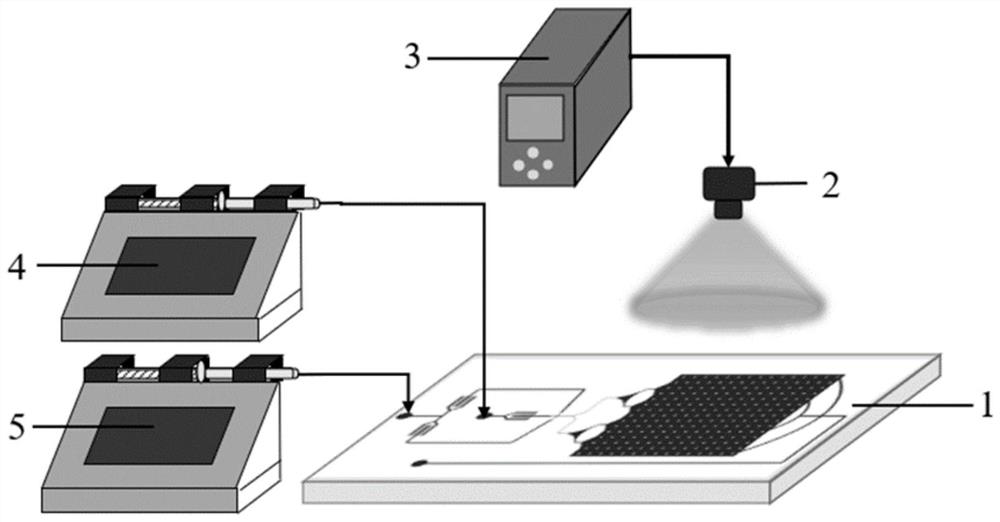
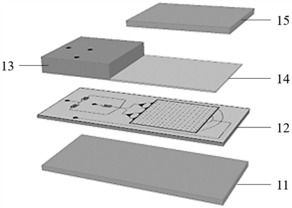
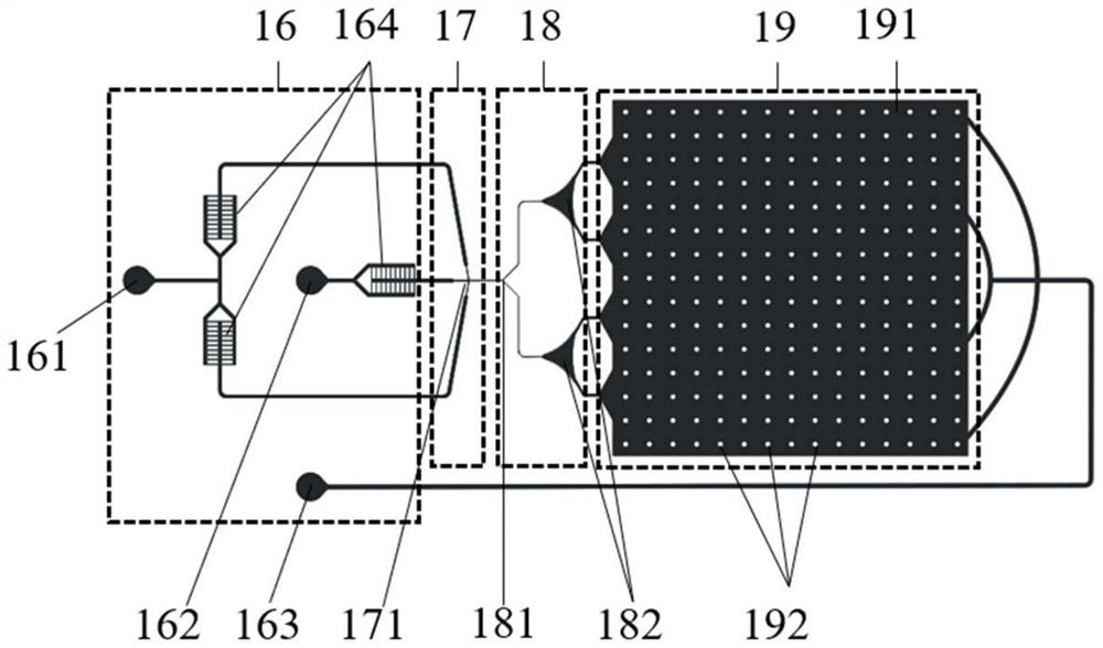
[0120] a) According to the channel structure of the main body of the microfluidic chip (such as image 3 ) custom masks;

[0121] b) Spin-coat photoresist (Microchem, SU-8 3025) on a clean single crystal silicon wafer with a thickness of 50 μm;

[0122] c) placing the mask on the silicon wafer coated with photoresist, and exposing it on an ultraviolet lithography machine;

[0123] d) developing, removing excess photoresist, and obtaining a mold with a photoresist pattern;

[0124] e) Mix the PDMS prepolymer and curing agent (Dow Corning, Sylgard184) in a ratio of 10:1, stir evenly, pour 6g onto the mold, and spin-coat it into a film with a thickness of 450 μm;

[0125] f) placing the mold spin-coated with a PDMS film with a thickness of 450 μm in step (e) on a heating plate for heating and curing;

[0126] g) Seal the blank PDMS support module to the top of the sample inlet and sample outlet area of ​​t...

Embodiment 2~4

[0146] The same process flow and raw material composition as in Example 1 are adopted, the only difference is that in step 4, the flow rate of the continuous phase is replaced by 100 μL / h, 60 μL / h, and 40 μL / h in sequence, and the diameters of the obtained droplets are 52 μm, 58μm vs. 72μm.

Embodiment 5

[0148] Using the same process flow as in Example 2, the only difference is that the raw material composition of the photocurable oil phase prepared in step 3 is different, specifically: by volume percentage, 91.5% polysiloxane acrylate (Gelest, UMS- 182), 5% stearate methacrylate (Sigma, 411442), 3% surfactant (Dow Corning, DC5225C), 0.5% photoinitiator 2-hydroxyl-2-methyl-1-phenyl-1 - Prepared by mixing acetone (Sigma, 405655).

[0149] After testing, this embodiment can generate stable droplets, and after the oil phase solidifies, the droplet array is fixed.


PUM


Abstract

The invention discloses a photocuring oil phase for preparing a droplet array chip. The photocuring oil phase comprises the raw materials: a photocuring reagent, a surfactant, a photopolymerization initiator and a diluent; the photocuring reagent is selected from at least one of a polymer containing a (methyl) acrylate functional group and a monomer containing a (methyl) acrylate functional group;and the surfactant is selected from a nonionic surfactant with a hydrophilic-lipophilic balance value of 2-8. The invention also discloses a preparation method for the droplet array chip by adoptinga photocuring mode by taking the photocuring oil phase as a raw material. The photocuring oil phase can form stable water-in-oil droplets with a water phase, and a large number of freely arranged water-in-oil droplets can be quickly fixed in situ only by several seconds of ultraviolet irradiation to form a stable droplet array. The photocuring oil phase is short in curing time, easy to store and more suitable for the ddPCR technology, and conditions are created for real-time fluorescence imaging detection due to the fact that the stable droplet array is formed.

Description

technical field [0001] The invention relates to the technical field of droplet microfluidics, in particular to a preparation method, product and application of a photocurable oil phase for preparing a droplet array chip and a photocurable droplet array chip. Background technique [0002] As a new generation of nucleic acid quantitative technology, digital polymerase chain reaction (Digital polymerase chain reaction, dPCR) has been developed very rapidly in recent years. The basic principle of dPCR is to dilute the sample to be tested and disperse it into a large number of independent reaction chambers, so that each reaction chamber contains 1 or 0 copies of the target molecule. The number of chambers can be used to obtain the concentration of nucleic acid. Compared with traditional quantitative PCR, dPCR has many unique advantages, including absolute quantification of nucleic acids, ultra-high sensitivity and accuracy, and is more suitable for complex sample analysis. It ha...

Claims


Application Information

Patent Timeline
IPC IPC(8): C08F283/00C08F220/18C08F283/12C08F222/14C08F222/20C08F283/06C08F220/24C08F2/48C12Q1/6851B01L3/00
CPCB01L3/502707B01L3/502784B01L2200/12B01L2300/0809B01L2300/12B01L2300/16C08F2/48C08F283/008C08F283/065C08F283/124C12Q1/6851C08F220/1818C08F220/1811C08F222/102C08F220/24C12Q2531/113C12Q2563/159C12Q2565/629
Inventor 张涛何宇
Owner ZHEJIANG UNIV
Why Eureka
Try Eureka