
Porous electrode for flow battery and preparation method of porous electrode

A porous electrode, flow battery technology, applied in battery electrodes, circuits, electrical components, etc., can solve problems such as sacrificing electrode transmission performance, and achieve the effect of ensuring mechanical properties, ensuring electrical conductivity, and improving battery performance

Active Publication Date: 2020-10-16
GUANGZHOU HKUST FOK YING TUNG RES INST
View PDF12 Cites 13 Cited by
  • Summary
  • Abstract
  • Description
  • Claims
  • Application Information

AI Technical Summary

Problems solved by technology

The traditional electrospun carbon fiber can provide a larger specific area due to its smaller fiber filament diameter, but at the same time it also sacrifices the transmission performance of the electrode, resulting in a large concentration polarization

Method used

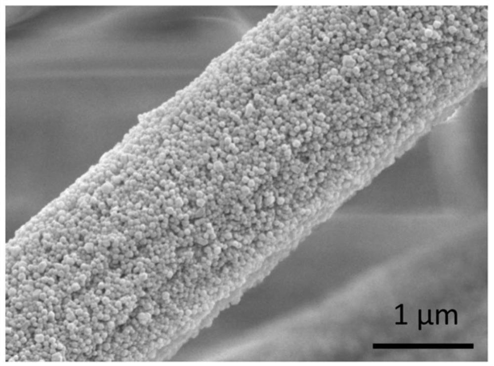
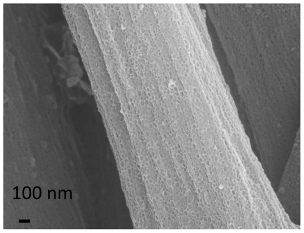
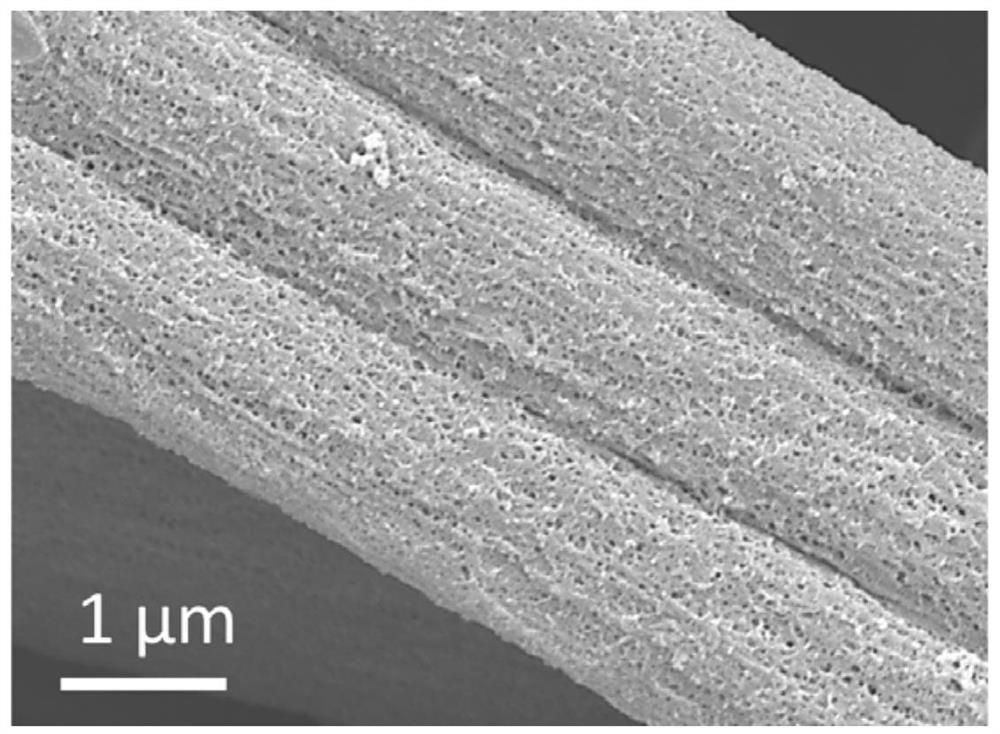

Image

  • Porous electrode for flow battery and preparation method of porous electrode
  • Porous electrode for flow battery and preparation method of porous electrode
  • Porous electrode for flow battery and preparation method of porous electrode

Examples


Embodiment 1

[0036] A porous electrode prepared by the following method:

[0037] (1) Mix 2g of polyacrylonitrile (PAN), 1g of zinc nitrate and 17g of N,N-dimethylformamide, heat and dissolve in a water bath at 70°C, and prepare an electrospinning stock solution.

[0038] (2) Take 15mL of the electrospinning stock solution from step 1, connect it to a 20G (0.60mm inner diameter) needle, and set the advancing speed of the electrospinning stock solution to 1.0mL h -1 , the electrospinning voltage was 17kV, the distance from the needle to the receiving end was 20cm, and the rotating speed of the receiving wheel was 200rpm. The ambient temperature of electrospinning was 25 °C and the relative humidity was 55%. The electrospun fiber membrane was removed after spinning for 10 h.

[0039](3) Weigh 1g of 2-methylimidazole and dissolve it in 200mL of a mixed solution of methanol and ethanol with a volume ratio of 1:1, cut the electrospun fiber membrane (4cm×4cm) in step 2 and soak it in the 2-met...

Embodiment 2

[0047] A porous electrode prepared by the following method:

[0048] (1) Weigh 2g of polyacrylonitrile, 1g of zinc acetate and 17g of N,N-dimethylformamide, mix them, heat and dissolve in a 70°C water bath, and prepare an electrospinning stock solution.

[0049] (2) Take 15mL of the electrospinning stock solution from step 1, connect it to a 20G (0.60mm inner diameter) needle, and set the advancing speed of the electrospinning stock solution to 1.0mL h -1 , the electrospinning voltage is 17kV, the distance from the needle to the receiving end is 20cm, and the rotating speed of the receiving wheel is 200rpm. The ambient temperature of electrospinning was 25 °C and the relative humidity was 55%. The electrospun fiber membrane was removed after spinning for 10 h.

[0050] (3) Weigh 1g of 2-methylimidazole and dissolve it in 200mL of a mixed solution of methanol and ethanol with a volume ratio of 1:1, cut the electrospun fiber membrane (4cm×4cm) in step 2 and soak it in the 2-me...


PUM

PropertyMeasurementUnit
Thicknessaaaaaaaaaa
Surface areaaaaaaaaaaa

Abstract

The invention provides a porous electrode for a flow battery and a preparation method of the porous electrode, and relates to the field of flow batteries. The preparation method comprises the following steps: S1, adding polyacrylonitrile and a metal salt into N, N-dimethylformamide or N, N-dimethylacetamide, carrying out heating and mixing until polyacrylonitrile and the metal salt are dissolved,so as to obtain an electrospinning stock solution; S2, carrying out electrostatic spinning by using the electrospinning stock solution to obtain an electrospun fiber membrane; S3, dissolving an organic ligand in a solvent to obtain an organic ligand solution, soaking the electrospun fibrous membrane in the organic ligand solution for a period of time, and generating MOF particles in situ on the surface of the electrospun fibrous yarn; and S4, carrying out pre-oxidation on the fibers with the MOF particles deposited on the surfaces, and then carrying out carbonization in an inert gas atmosphereto obtain the porous electrode. The porous electrode prepared in the invention has a large specific surface area, is helpful for reducing the activation loss of the battery and improving the performance of the battery, and can be suitable for various flow batteries.

Description

technical field [0001] The invention relates to the field of flow batteries, in particular to a porous electrode for a flow battery and a preparation method thereof. Background technique [0002] With the increasing problems of environmental pollution, climate warming and energy shortage, the proportion of clean and renewable energy in the total global power generation is gradually increasing, mainly including wind power and solar power generation. However, due to the influence of time, weather and other factors, wind power and solar power generation have intermittent and fluctuating power generation. In order to improve the stability of grid-connected renewable energy power generation, it is necessary to use energy storage systems to coordinate between wind energy, photovoltaic power generation and the grid. At present, the main energy storage systems include pumped hydro storage, compressed air energy storage, and battery energy storage. Among them, battery energy storage...

Claims


Application Information

Patent Timeline
IPC IPC(8): H01M4/88H01M4/86H01M4/96D01D5/00D01F9/22D01F11/14D04H1/43D04H1/728D06C7/04
CPCD01D5/003D01D5/0092D01F9/22D01F11/14D04H1/43D04H1/728D06C7/04H01M4/8605H01M4/8817H01M4/8875H01M4/96Y02E60/50
Inventor 赵天寿孙静范新庄
Owner GUANGZHOU HKUST FOK YING TUNG RES INST
Learn More