Double-line double-end bulk current injection equivalent strong-field continuous wave radiation effect test and system

A technology of wave radiation and high current, applied in the field of electromagnetic radiation effect test, can solve the problems of hard damage, scrapping of equipment, failure of equipment to maintain normal work, etc., and achieve the effect of solving limitations

Active Publication Date: 2021-02-05
ARMY ENG UNIV OF PLA
View PDF15 Cites 6 Cited by
  • Summary
  • Abstract
  • Description
  • Claims
  • Application Information

AI Technical Summary

Problems solved by technology

[0002] With the development of science and technology, frequency-using equipment in various fields is increasing, including high-power frequency-using equipment. Especially in the military field, with the use of strong electromagnetic pulse weapons and high-power frequency-using equipment, the location of equipment The electromagnetic environment is becoming increasingly harsh; this high-intensity radiation field (HIRF) interference may make the equipment unable to maintain normal work, not only that, it may also cause hard damage or even scrap the equipment; therefore, through the electromagnetic radiation effect on the equipment Tests to evaluate the safety performance of equipment are becoming more and more urgent; the current requirements for electromagnetic compatibility and field strength test standards for electromagnetic radiation sensitivity are constantly improving. GJB1389A-2005 pointed out that the harsh electromagnetic environment faced by army helicopters is in the 2.7-3.6GHz frequency band The internal peak field strength may be as high as 27460V / m, and the peak field strength exceeds 2000V / m in most frequency bands; usually, the electromagnetic interference coupling channels of weaponry mainly include: antennas, cables, holes, shielding transmission, etc. ; Nowadays, most advanced weapon systems in various countries tend to be functionally integrated and complex, with various electronic devices all over the interior, and cables are often used to interconnect each device or subsystem to achieve information transmission or power transmission; the interconnection system relies on cables As a result, the cable coupling channel has become one of the weak links in the electromagnetic protection of the interconnection system; therefore, whether the electromagnetic interference introduced by the interconnection cable coupling will lead to the generation of electromagnetic effects must be evaluated in advance through the strong field electromagnetic environment effect test; however, the traditional Due to the limitations of the full-level electromagnetic radiation test method, it is unrealistic to simulate such a high-field electromagnetic environment under current laboratory conditions, and it is even more difficult to simulate a large spatial range; how to Responding to the contradiction between the laboratory electromagnetic environment simulation conditions and the electromagnetic compatibility test requirements is the top priority in the research of electromagnetic radiation effect testing; in this context, the method of using current injection to replace radiation sensitivity came into being, and It has gradually been applied and developed in many fields; however, the current current injection method is mainly used for conduction sensitivity test, and there are relatively few studies on its use in equivalent radiation sensitivity test; the current injection method mainly includes large current injection ( BCI) method, direct current injection (DCI) method and pulsed current injection (PCI) method, etc.; BCI is a common mode injection method using a ferrite injection probe, and the interference signal is first coupled to the interconnection cable through the injection probe, and further The EUT coupled to the cable terminal in a conductive manner; as a conductive susceptibility test method, BCI has been widely accepted, especially in the military and automotive industries; A series of test methods for electromagnetic safety verification; Among them, for the case where the cable is the coupling path, it is proposed to use the large current injection method (BCI) to carry out the equivalent test; the current injection method has the advantages of high efficiency and good repeatability, and can be used in a certain Under the limited conditions, this method has high engineering application value; however, this method also has its own problems, the most important of which is about the nonlinear response of the equipment under test (EUT). The method of linear extrapolation of the relationship between induced currents may lead to large errors in the test; usually, only one BCI injection probe is used on the same interconnection cable in the test of BCI used for radiation susceptibility assessment; this kind of test The configuration is suitable for the case where only one end of the interconnection cable is connected to the EUT, and the other end of the cable is connected to auxiliary equipment, and its electromagnetic susceptibility generally does not need to be assessed; however, sometimes the electromagnetic susceptibility of the equipment at both ends of the cable needs to be assessed at the same time. If only one injection probe is used, it is impossible to ensure that the response of the 
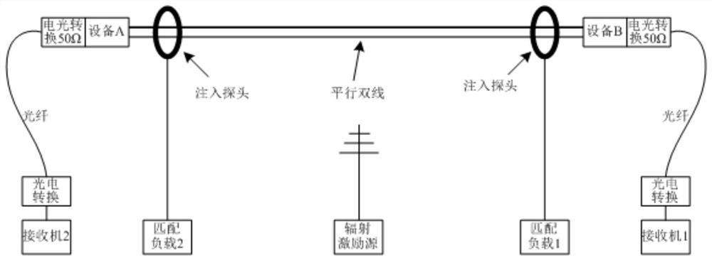
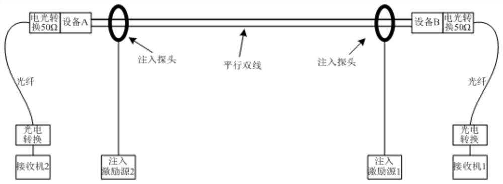
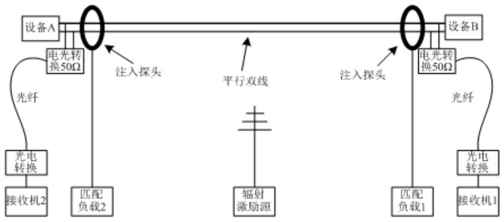
equipment under test at both ends can be consistent with the radiation test under general conditions; to solve this problem, SergioPignari et al. proposed a double-ended high current injection technology; this technology is in An injection probe is connected to each end of the cable. By controlling the amplitude and phase difference of the two injection voltage sources, it can ensure that the response of the equipment at both ends of the cable is consistent with the radiation time; this method obtains the parameters of the injection source through calculation, so the test results The accuracy largely depends on whether the relevant system parameter values ​​can be accurately known in advance, and these parameters are difficult to obtain accurately in engineering tests; in addition, the existing double-terminal high current injection technology still does not consider how to generate In the case of nonlinear response, the equivalent of strong electric field radiation effect test is realized; parallel twin wires and twisted pair wires are commonly used cables in engineering, how to carry out high current injection equivalent for the two-wire interconnection system where the equipment at both ends is nonlinear Strong field radiation effect test is a key technical problem to be solved

Method used


Image

  • Double-line double-end bulk current injection equivalent strong-field continuous wave radiation effect test and system
  • Double-line double-end bulk current injection equivalent strong-field continuous wave radiation effect test and system
  • Double-line double-end bulk current injection equivalent strong-field continuous wave radiation effect test and system

Examples


Embodiment 1

[0034] like Figure 1 to Figure 7 As shown, a double-wire double-terminal large current injection equivalent strong field continuous wave radiation effect test and system, the method includes the following steps:

[0035] 1) Monitor the equipment at both ends of the cable. When there is no monitorable output response from the equipment at both ends of the cable, connect the photoelectric conversion device to the two terminals of the cable in parallel, and connect the output of the photoelectric conversion device to the receiver. For the cable If the output response of the equipment at both ends can be monitored, its output is connected to the receiver through the photoelectric conversion equipment;

[0036] 2) Carry out injection pre-test, for each test frequency point, adjust the position of the two injection probes on the cable to maximize the injection efficiency;

[0037] 3) Carry out the low-field-strength electromagnetic radiation pre-test, select the appropriate radiat...

Embodiment 2

[0048] Taking the parallel two-wire interconnection system as an example to verify the effectiveness of this test method, in order to verify the accuracy of the test method when the impedance of the equipment port at both ends of the cable changes significantly, the test is carried out by artificially changing the impedance of the equipment under test. The details are as follows : Use the pass-through load as the test equipment at both ends of the cable, connect the pass-through loads with different resistance values ​​at both ends of the cable during the high and low field intensity radiation test, and simulate the change of the port impedance of the test equipment during the high-field electromagnetic radiation test Happening;

[0049] like Image 6 and Figure 7 As shown in Fig. 1; the situation that the equipment under test does not have an output response that can be easily monitored is taken as an example for verification. The test is carried out in an anechoic chamber....


PUM


Abstract

The invention discloses a double-line equivalent strong-field continuous wave radiation effect test. The method comprises the following steps: (1) monitoring equipment at two ends of a cable; (2) carrying out an injection pre-test; (3) carrying out a low-field-intensity electromagnetic radiation pre-test; (4) carrying out an equivalent injection test; and (5) acquiring an injection test result equivalent to that of a strong-field electromagnetic radiation test; the system corresponding to the method comprises a double-line radiation test and double-line injection test configuration module whenthe terminal equipment responds to a monitorable state, and a double-line low-field-intensity radiation test and double-line injection equivalent low-field-intensity radiation test configuration module when the terminal equipment responds to an unmonitorable state. The double-line double-end bulk current injection equivalent strong-field continuous wave radiation effect test and system are mainlyused for an interconnection system of which the interconnection cable is a parallel wire or a twisted pair, and the method has the advantage that the equivalent strong-field electromagnetic radiationtest can be carried out under the condition that the response of tested equipment is non-linear.

Description

technical field [0001] The invention relates to a continuous wave electromagnetic radiation effect test method, in particular to a double-wire double-terminal high current injection equivalent strong field continuous wave radiation effect test and system, which belongs to the technical field of electromagnetic radiation effect test. Background technique [0002] With the development of science and technology, frequency-using equipment in various fields is increasing, including high-power frequency-using equipment. Especially in the military field, with the use of strong electromagnetic pulse weapons and high-power frequency-using equipment, the location of equipment The electromagnetic environment is becoming increasingly harsh; this high-intensity radiation field (HIRF) interference may make the equipment unable to maintain normal work, not only that, it may also cause hard damage or even scrap the equipment; therefore, through the electromagnetic radiation effect on the equ...

Claims


Application Information

Patent Timeline
Patent Type & Authority Applications(China)
IPC IPC(8): G01R29/08G01R31/00F41A31/00
CPCG01R29/0814G01R31/001F41A31/00
Inventor 潘晓东万浩江卢新福魏光辉孙江宁
Owner ARMY ENG UNIV OF PLA
Why Eureka
Try Eureka