Method for separating refinery saturated dry gas

A dry gas and refinery technology, applied in the petroleum industry, hydrotreating process, processing hydrocarbon oil, etc., can solve the problems of large desorption load, large comprehensive energy consumption, and high comprehensive energy consumption, and achieves reduction of desorption load and equipment. The effect of energy consumption and equipment investment reduction

Active Publication Date: 2021-02-26
山东中泰化学科技有限公司
View PDF6 Cites 0 Cited by
  • Summary
  • Abstract
  • Description
  • Claims
  • Application Information

AI Technical Summary

Problems solved by technology

[0007] Patent CN 109553504 A proposes a method and device for recovering saturated dry gas in a refinery using shallow cold oil absorption technology. The process consists of steps such as compression, absorption, desorption, and reabsorption and desorption. The conditions are mild, but due to the high absorption temperature, the amount of solvent circulation is high, the energy consumption of the device is high, and the content of C3 and heavy components in the absorbed methane hydrogen is high, resulting in the need for two sets of absorption-desorption systems, making the process complicated
[0008] Patents CN 106609160 B and CN 106608795 B propose a method for separating coking dry gas, and obtain ethane products through catalytic hydrogenation and absorption. Due to the method of shallow cooling oil absorption, the process has a large amount of solvent circulation and comprehensive energy consumption high
[0009] Patent CN 104892340 A discloses a three-tower device and method for oil absorption of dry gas to recover ethylene and ethane, by adding cooling and flash evaporation before the desorption tower and reducing the operating temperature of absorption to improve the recovery of methane rate to reduce the methane content in ethylene products, but the technical essence of cooling and flashing is equivalent to adding a desorption tower top dephlegmator system, and the flash tank is equivalent to the gas-liquid buffer tank after the desorption tower, which is equivalent to Because of the separation of secondary methane and ethylene by means of fractional condensation, the purpose of improving the recovery rate of methane has been realized, but the problem of high energy consumption of the process has not been solved
[0010] Patent CN 101063048 A discloses a method for separating refinery dry gas by intercooler oil absorption method. The process consists of compression, dry gas pretreatment, absorption, desorption, cooling recovery and rough separation. The liquefied gas is used as the absorbent, and the cold box-expander system is set to recover the lost absorbent and carbon dioxide. It has the advantages of low cost of absorbent, low loss, high recovery rate of carbon dioxide, and no need for ethylene refrigeration compressors. However, In this process, all the absorbents use the bottom of the desorption tower to circulate the poor solvent, and the recovered carbon dioxide is obtained by thermal desorption of the desorption tower, resulting in a large amount of poor solvent circulation, large desorption load, high energy consumption of the device, and large equipment investment
[0011] In summary, the existing methods for separating saturated dry gas in refineries all have the problems of large solvent circulation, high investment, and large comprehensive energy consumption

Method used


Image

  • Method for separating refinery saturated dry gas

Examples


Embodiment Construction

[0040] The technical solution of the present invention will be clearly and completely described below. Apparently, the described embodiments are only some of the embodiments of the present invention, not all of them. Based on the embodiments of the present invention, all other embodiments that are improved or adjusted by those skilled in the art belong to the protection scope of the present invention.

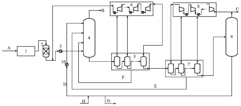
[0041] by figure 1 As an example, describe a method for separating saturated dry gas in a refinery provided by the present invention, in which the dry gas precooling heat exchanger, multi-stage absorption tower intercooler, circulating dry gas compression stages, carbon dioxide enriched gas compressor stage Number, flash tanks in high pressure area and flash tanks in low pressure area can be set up as many as required. Two tanks are set up, and the circulating dry gas compression system and the carbon dioxide enriched gas compression system are set up at three levels, and in ...


PUM


Abstract

The invention belongs to the technical field of refinery dry gas recovery, and provides a method for separating refinery saturated dry gas, which comprises the following steps: sequentially carrying out pretreatment, catalytic hydrogenation treatment and cooling treatment on the saturated dry gas, feeding the treated saturated dry gas into a multistage absorption tower, carrying out absorption treatment with a C4 absorbent, feeding a gas phase of the multistage absorption tower into a fuel gas pipe network or a PSA device, and feeding a liquid phase into a high-pressure flash evaporation areafor treatment; compressing a gas phase of the high-pressure flash evaporation area and returning the compressed gas phase to the multi-stage absorption tower, and feeding a liquid phase of the high-pressure flash evaporation area into the multi-stage absorption tower and a low-pressure flash evaporation area; feeding a gas phase of the low-pressure flash evaporation area into a C2 concentrated gascompressor system, and feeding a liquid phase of the low-pressure flash evaporation area into the multi-stage absorption tower and a C2 desorption tower; and mixing a gas phase of the C2 desorption tower and a gas phase of the low-pressure flash evaporation area to serve as a C2 concentrated gas product, returning most of a liquid phase serving as a lean solvent to the multi-stage absorption tower, and sending a small part of the liquid phase serving as extracted C4 to be sent out of the boundary. The process provided by the invention has the advantages of simple flow, low lean solvent consumption, low energy consumption, low investment, high C2-C3 recovery rate and the like.

Description

technical field [0001] The invention belongs to the technical field of refinery dry gas recovery, and in particular relates to a method for separating saturated dry gas in a refinery. Background technique [0002] The dry gas mainly comes from the processing process of the refining unit and chemical unit in the refinery. The dry gas of the refining unit mainly comes from the primary and secondary processing of crude oil, such as atmospheric and vacuum distillation unit, catalytic cracking unit, catalytic cracking unit, delayed Coking units, etc. The main sources of dry gas in chemical plants are alkane dehydrogenation units, PSA units, light hydrocarbon recovery units, ethylbenzene-styrene units, etc. At present, the dry gas produced by most refineries in my country is burned as fuel, and some are even put into torches for burning, which has low utilization value and causes serious waste of resources and environmental pollution. [0003] Dry gas is usually divided into satu...

Claims


Application Information

Patent Timeline
Patent Type & Authority Applications(China)
IPC IPC(8): C10G67/04
CPCC10G67/04
Inventor 候国新邹雄朱炜玄韩志忠董宏光
Owner 山东中泰化学科技有限公司
Why Eureka
Try Eureka