

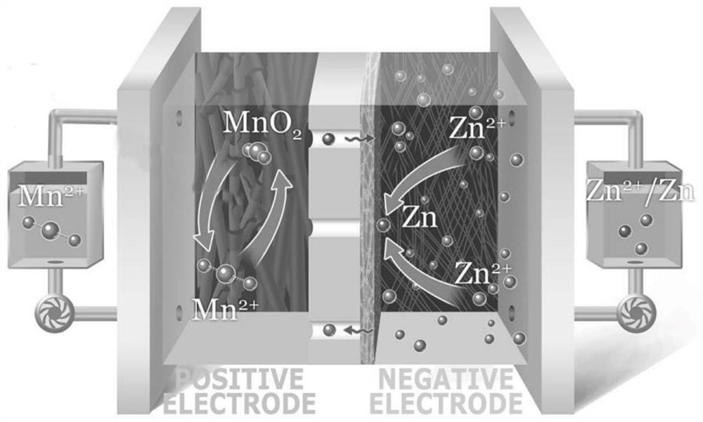
Neutral zinc-manganese secondary battery and electrolyte
A secondary battery and electrolyte technology, applied in the field of batteries and zinc-manganese secondary batteries, can solve the problems of battery capacity decay, heavy corrosion of zinc negative electrode, low battery specific capacity, etc., and achieve the effect of improving cycle life
- Summary
- Abstract
- Description
- Claims
- Application Information
AI Technical Summary
Problems solved by technology
Method used
Image

Examples
Embodiment Construction
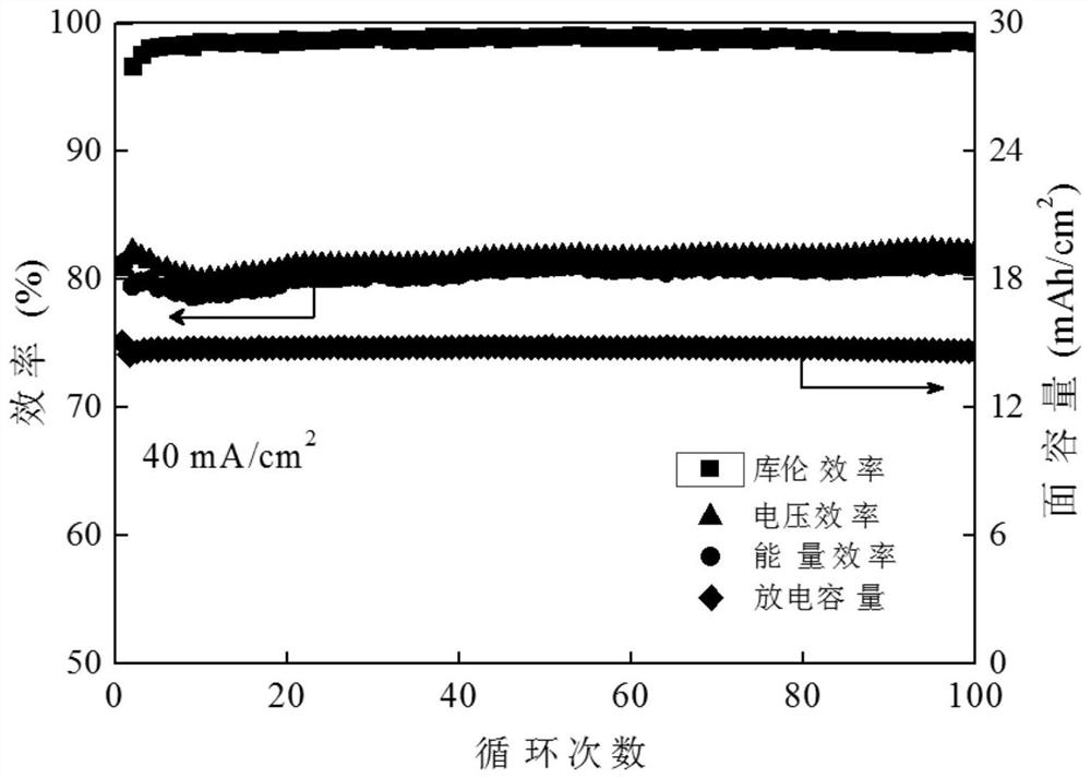
[0047]Examples 1-24 are a zinc manganese liquid flow battery assembled in a single battery, and the single battery sequentially includes a positive electrode end plate, a positive electrode fluid, a carbon felt positive electrode having a liquid flow frame, a liquid flow frame. Felt negatives, negative electrode concentration fluids, negative electrode plates, electrolytic liquid tanks and pumps with positive, negative electrolytes. Electrolytic flow rate is 10 ml / min, charge current is 40mA / cm2The cutoff condition of the battery is time-off, and the charging deadline is 10 ~ 30mins, the safety voltage is set to 2.3V, the discharge voltage is 0.1V.
[0048]Electrode area 48cm2The carbon felt has a thickness of 5 mm, a compression ratio of 30%.
[0049]
[0050]
[0051]
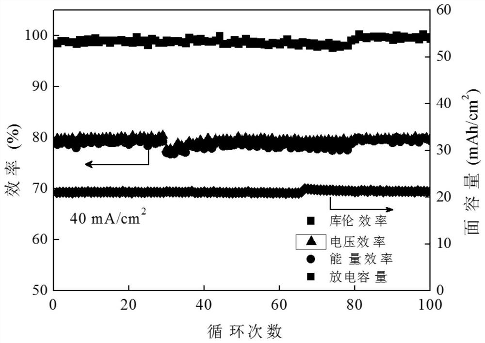
[0052]image 3 (Example 2) is a circulating performance-capacity retention ratio of the battery under optimal conditions (the ratio of acetate anion and manganese ions is 4: 1, 1m zinc ion and manganese ion concentration) batt...
PUM
| Property | Measurement | Unit |
|---|---|---|
| pore size | aaaaa | aaaaa |
| area | aaaaa | aaaaa |
| thickness | aaaaa | aaaaa |
Abstract
Description
Claims
Application Information