Super-smooth nickel-titanium alloy intracranial vascular stent with micro-nano structure
A technology of intracranial blood vessels and micro-nano structures, applied in the field of medical devices, can solve the problems of non-adhesion, protruding into aneurysms, and poor adhesion, so as to prevent crushing or collapse, promote vascular endothelialization, and adherence good effect
- Summary
- Abstract
- Description
- Claims
- Application Information
AI Technical Summary
Problems solved by technology
Method used
Image
Examples
Embodiment 1
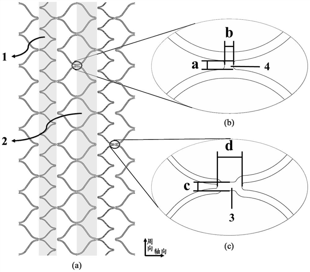
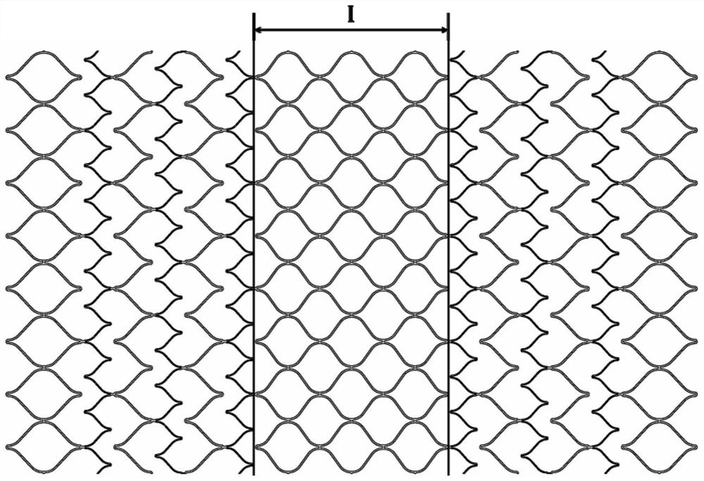
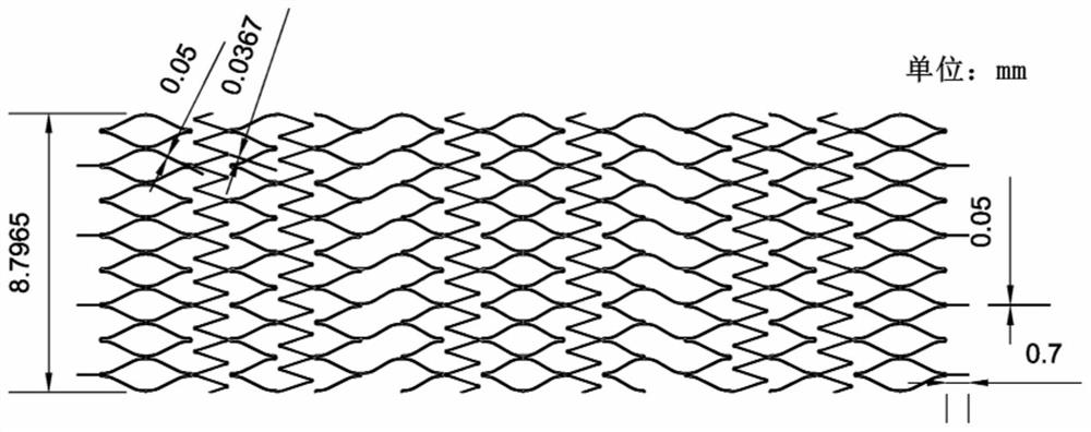
[0044] In this example, a super-compliant nickel-titanium alloy intracranial vascular stent with a micro-nano structure is designed. The middle part of the design is locally reinforced with a closed-loop structure, and the length is 2.25 mm; the open-loop structure accounts for 30% of the surface area of the entire intracranial vascular stent. ; The second V-shaped unit 2 wire width is 0.05mm, the first V-shaped unit 1 wire width is 0.0367mm, the connecting rod (b) height a is 0.05mm, the width b is 0.05mm, and the connecting rod (c) height c is 0.06mm, width d is 0.0857mm. The ratio of the length dimension to the width dimension of the first V-shaped unit 1 is 0.84, and the ratio of the height dimension to the width dimension of the second V-shaped unit 2 is 0.6-0.7.
[0045] Such as image 3 As shown, the plane unfolded cutting diagram of the intracranial vascular stent. According to the design drawings, the final intracranial vascular stent can be prepared by laser cutt...
Embodiment 2
[0047] In this embodiment, a three-point bending test is performed on the stent processed in Example 1 to characterize the flexibility of the stent. The three-point bending test equipment consists of two lower fixed support parts (parallel cylinders with a diameter of 4 mm) and an upper loading part (a cylinder with a diameter of 4 mm). The fixed-span three-point bending method is adopted, and the span of the lower fixed support part is set to 20mm. Proceed as follows:
[0048] a) Assembly lofting: place the sample perpendicular to the fixed support parts, assemble the loading part parallel to the fixed support parts, and make it in the middle of the two fixed support parts.
[0049] b) Start-up test: load is applied at a constant rate of 0.05 mm / s up to a predetermined maximum deflection of 4.5 mm.
[0050] c) Record whether the sample exhibits sufficiently uniform bending throughout the test, and plot the load versus deflection curve.
[0051] Such as Figure 5 Test resu...
Embodiment 3
[0053] In this embodiment, during the process of release and compression, the relationship between the radial support force of the stent processed in Example 1 and the diameter of the stent was measured to characterize the support performance of the stent. Using radial crimping method and plate method respectively:
[0054] 1. Radial crimping method:
[0055] a) Place the bracket into the device, and the initial aperture of the device is set to 7mm;
[0056] b) Reduce the diameter of the stent to 0.5mm at a rate of 0.0156mm / s;
[0057] c) Then the aperture increases at a rate of 0.0156mm / s, and the bracket is slowly unloaded to 4.5mm;
[0058] d) During the stent crimping process, the relationship between radial force and stent diameter is recorded.
[0059] 2. Plate method:
[0060] a) Place the bracket between the two plates, and make it in the center of the component, and adjust the pressure head to just stick to the surface of the bracket;
[0061] b) Apply a load at ...
PUM
 Abstract
Description
Claims
Application Information
 - R&D
- Intellectual Property
- Life Sciences
- Materials
- Tech Scout
- Unparalleled Data Quality
- Higher Quality Content
- 60% Fewer Hallucinations
Browse by: Latest US Patents, China's latest patents, Technical Efficacy Thesaurus, Application Domain, Technology Topic, Popular Technical Reports.
© 2025 PatSnap. All rights reserved.Legal|Privacy policy|Modern Slavery Act Transparency Statement|Sitemap|About US| Contact US: help@patsnap.com


